Registered User |
Registered User mNo edit summary Tag: 2017 source edit |
||
| (31 intermediate revisions by 4 users not shown) | |||
| Line 2: | Line 2: | ||
This tutorial helps to: | This tutorial helps to: | ||
:*Use the X-NUCLEO-SNK1M1 | :*Use the X-NUCLEO-SNK1M1 shield that includes a TCPP01-M12 protection circuit and provides a USB Type-C<sup>®</sup> connector | ||
:*Create a USB-PD Sink | :*Create a USB-PD Sink device with the NUCLEO-G071RB board and the X-NUCLEO-SNK1M1 using STM32CubeMX software<br> | ||
<big><big>'''Prerequisites'''</big></big><br> | <big><big>'''Prerequisites'''</big></big><br> | ||
| Line 12: | Line 12: | ||
:*'''NUCLEO-G071RB''' (tested on rev B01) <ref>[https://www.st.com/en/evaluation-tools/nucleo-g071rb.html NUCLEO-G071RB]</ref> | :*'''NUCLEO-G071RB''' (tested on rev B01) <ref>[https://www.st.com/en/evaluation-tools/nucleo-g071rb.html NUCLEO-G071RB]</ref> | ||
:*'''X-NUCLEO-SNK1M1''' (tested on Rev 1) <ref>[https://www.st.com/en/ecosystems/x-nucleo-snk1m1.html X-NUCLEO-SNK1M1 | :*'''X-NUCLEO-SNK1M1''' (tested on Rev 1) <ref>[https://www.st.com/en/ecosystems/x-nucleo-snk1m1.html X-NUCLEO-SNK1M1]</ref> | ||
:*A '''USB-PD source device''' to test our USB-PD device (it can be a PD capable wall charger, a power bank, etc.) | :*A '''USB-PD source device''' to test our USB-PD device (it can be a PD capable wall charger, a power bank, etc.) | ||
:*USB cable Type-A to Micro-B | :*USB cable Type-A to Micro-B | ||
:*USB Type-C<sup>®</sup> cable | :*USB Type-C<sup>®</sup> to Type-C<sup>®</sup> cable | ||
<big><big>'''Software'''</big></big><br> | <big><big>'''Software'''</big></big><br> | ||
:*'''STM32CubeIDE''' (tested with V1. | :*'''STM32CubeMX''' (tested with V6.11.0 - minimal release 6.11.0) <ref>[https://www.st.com/en/development-tools/stm32cubemx.html STM32CubeMX]</ref> | ||
:*'''STM32CubeMonitor-UCPD''' (tested with V1. | :*'''STM32CubeIDE''' (tested with V1.14.0) <ref>[https://www.st.com/en/development-tools/stm32cubeide.html STM32CubeIDE]</ref> | ||
:*X-CUBE-TCPP MCU Firmware Package ( | :*'''STM32CubeMonitor-UCPD''' (tested with V1.3.0) <ref>[https://www.st.com/en/development-tools/stm32cubemonucpd.html STM32CubeMonitor-UCPD]</ref> | ||
:*X-CUBE-TCPP MCU Firmware Package (BSP) <ref>[https://github.com/STMicroelectronics/x-cube-tcpp X-CUBE-TCPP]</ref> | |||
<big><big>'''Literature'''</big></big><br> | <big><big>'''Literature'''</big></big><br> | ||
:*[https://www.st.com/resource/en/user_manual/um2324-stm32-nucleo64-boards-mb1360-stmicroelectronics.pdf UM2324] NUCLEO-G071RB User Manual | :*[https://www.st.com/resource/en/user_manual/um2324-stm32-nucleo64-boards-mb1360-stmicroelectronics.pdf UM2324] NUCLEO-G071RB User Manual | ||
:*[https://www.st.com/resource/en/user_manual/um2773-getting-started-with-the-xnucleosnk1m1-usb-typec-power-delivery-sink-expansion-board-based-on-tcpp01m12-for-stm32-nucleo-stmicroelectronics.pdf UM2773] X-NUCLEO-SNK1M1 User Manual | :*[https://www.st.com/resource/en/user_manual/um2773-getting-started-with-the-xnucleosnk1m1-usb-typec-power-delivery-sink-expansion-board-based-on-tcpp01m12-for-stm32-nucleo-stmicroelectronics.pdf UM2773] X-NUCLEO-SNK1M1 User Manual | ||
:*[[File:pc_videol.png|middle|20px|link=https://www.youtube.com/watch?v=cbdFHmMOMwk]] [https://www.youtube.com/watch?v=cbdFHmMOMwk How to build an USBPD Sink application using the X-Cube-TCPP software pack] | |||
:*[[File:pc_videol.png|middle|20px|link=https://www.youtube.com/watch?v= | |||
| Line 36: | Line 35: | ||
[[File:Clock.png|40px|middle]] Total 45min<br><br> | [[File:Clock.png|40px|middle]] Total 45min<br><br> | ||
=Creating the project= | ==Software pack installation== | ||
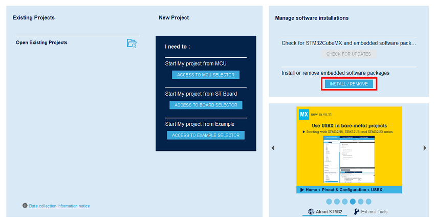
Open STM32CubeMX, in the software pack area, click on the ''install/remove'' button. | |||
[[File:STM32StepByStep_Install SP 1bis.png|center]]<br> | |||
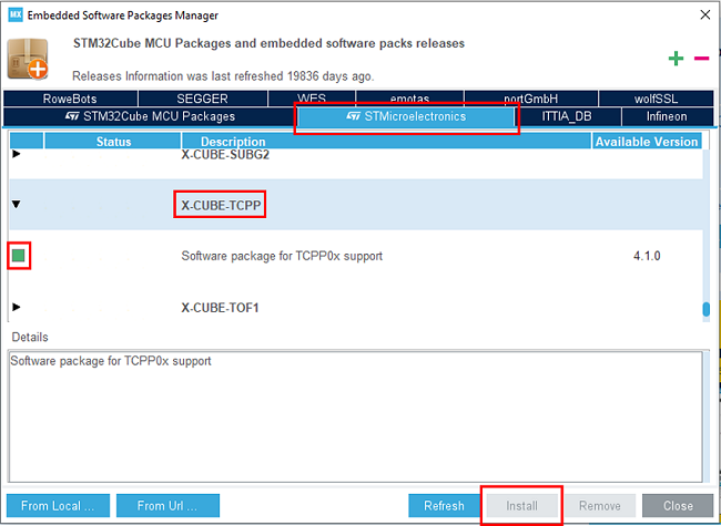
Then select the ''STMicroelectronics'' tab, scroll down to the ''X-Cube-TCPP'' software pack, and click on the ''install'' button if it is not already installed. | |||
[[File:STM32StepByStep_Install SP 2.png|center]]<br> | |||
==Creating the project== | |||
[[File:Clock.png|40px|middle]] 5min<br><br> | [[File:Clock.png|40px|middle]] 5min<br><br> | ||
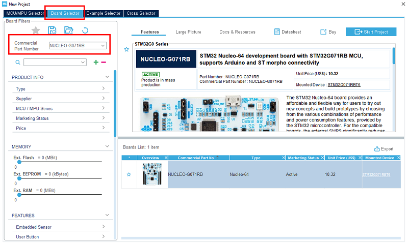
In STM32CubeMX, create a new STM32 project. As a target selection, choose the NUCLEO-G071RB from the ''Board Selector'' Tab.<br> | |||
[[File:STM32StepByStep_03 Start Project_G0.png|center]]<br> | |||
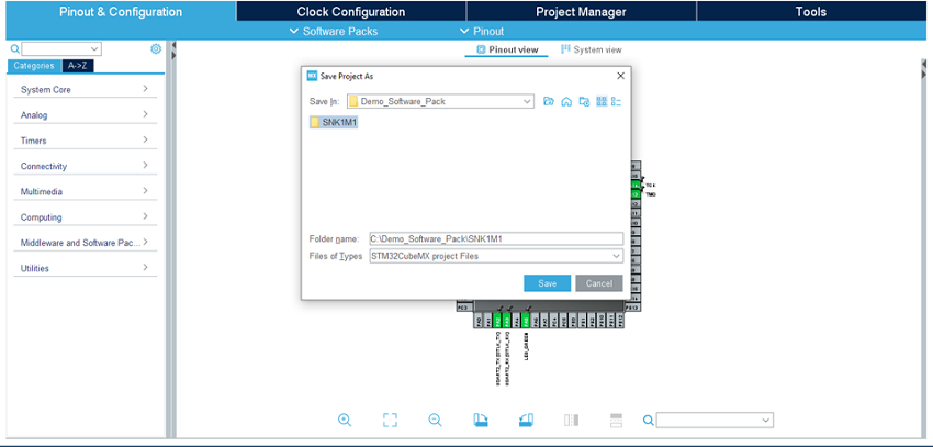
[[File: | Click "Start Project", then in the file menu, create a new folder under your project's name, and click "Save". | ||
[[File:STM32StepByStep_04 Save Project as.png|center]]<br> | |||
When prompted for initializing peripherals with their default mode, click No. | |||
=Configuring the system= | ==Configuring the system== | ||
[[File:Clock.png|40px|middle]] 15min<br><br> | [[File:Clock.png|40px|middle]] 15min<br><br> | ||
At this point, your project is created | At this point, your project is created. The next steps show how to configure the peripherals and options needed for the project. | ||
<br><br> | <br><br> | ||
==Configure UCPD peripheral== | ===Clear the pinout=== | ||
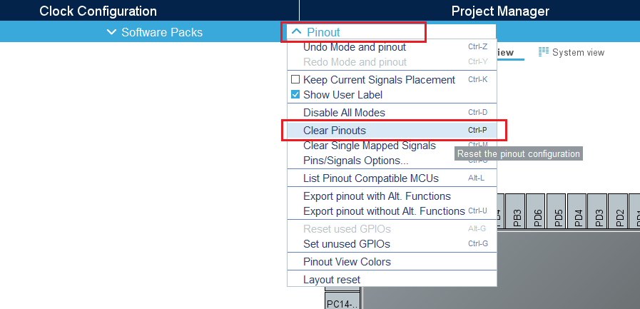
To start from a blank configuration, click on the ''Pinout'' menu and select ''Clear Pinouts''. This will reset the pinouts in the Pinout view. | |||
[[File:USBPD_0-pinoutConf.png|frame|center]]<br> | |||
===Select the X-CUBE-TCPP software pack=== | |||
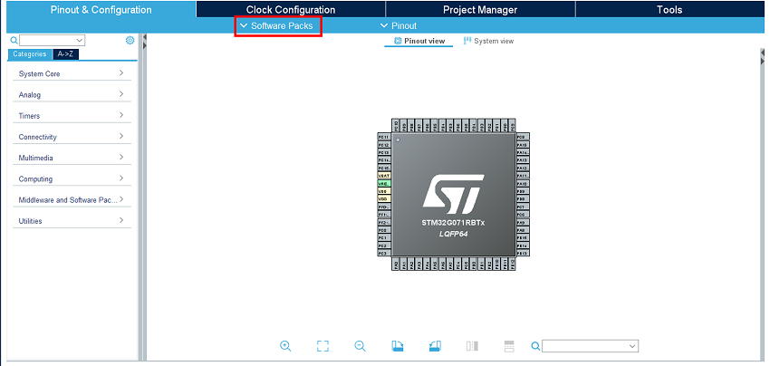
From the software pack menu: | |||
[[File:STM32StepByStep_SP Menu v4.png|center]]<br> | |||
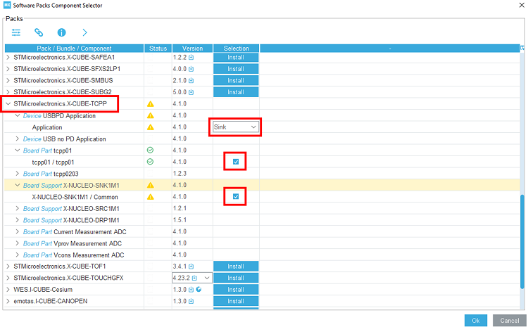
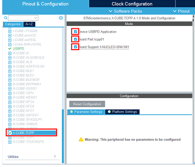
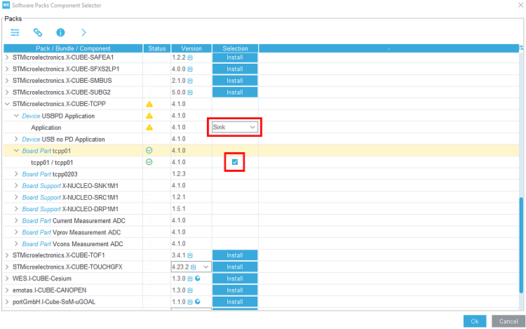
Select the X-CUBE-TCPP Software pack and enable its ''Sink'' application, the ''tcpp01'' board part, and the ''X-NUCLEO-SNK1M1'' board support. | |||
[[File:STM32StepByStep_06 SP Select SNK.png|center]]<br> | |||
===Configure UCPD peripheral=== | |||
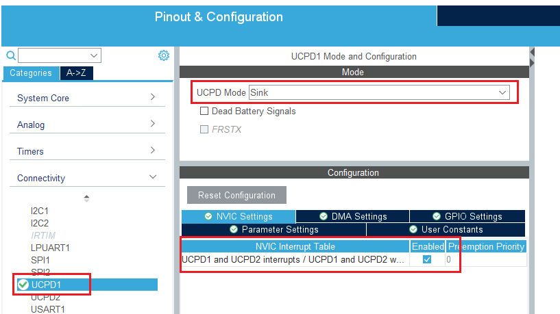
In the ''Connectivity'' tab, select the ''UCPD1'' peripheral and enable it in sink mode. Under the ''NVIC Settings'' tab, enable UCPD global interrupts. | In the ''Connectivity'' tab, select the ''UCPD1'' peripheral and enable it in sink mode. Under the ''NVIC Settings'' tab, enable UCPD global interrupts. | ||
{{Info | You do not need to include “Dead Battery Signals” in the configuration as this is managed by the TCPP01 protection device on the X-NUCLEO-SNK1M1 shield.}} | {{Info | You do not need to include “Dead Battery Signals” in the configuration as this is managed by the TCPP01 protection device on the X-NUCLEO-SNK1M1 shield.}} | ||
[[File:snk0-UCPD1Conf.png|frame|center]]<br> | [[File:snk0-UCPD1Conf.png|frame|center]]<br> | ||
Under the ''DMA Settings'' tab, add UCPD1_RX and UCPD1_TX DMA requests. | Under the ''DMA Settings'' tab, add UCPD1_RX and UCPD1_TX DMA requests. Select '''DMA1 channel 4 for RX''' and '''DMA1 channel 2 for TX'''. | ||
[[File: | [[File:USBPD_1-UCPD1Conf.png|frame|center]]<br> | ||
==Configure FreeRTOS Middleware== | ===Configure FreeRTOS Middleware=== | ||
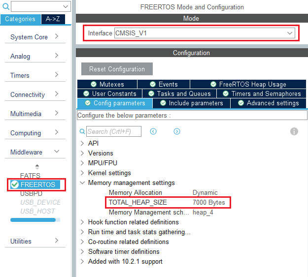
In the ''Middleware'' section, enable ''FreeRTOS'' with ''CMSIS_V1'' interface. Under the ''Config Parameters'' tab, change "TOTAL_HEAP_SIZE" to 7000 bytes. | In the ''Middleware'' section, enable ''FreeRTOS'' with ''CMSIS_V1'' interface. Under the ''Config Parameters'' tab, change "TOTAL_HEAP_SIZE" to 7000 bytes. | ||
[[File:0-FreeRTOSConf.png|frame|center]]<br> | [[File:0-FreeRTOSConf.png|frame|center]]<br> | ||
Then, under the ''Include Parameters'' tab, Enable ''eTaskGetState'' include definition. | <!-- OK by default Then, under the ''Include Parameters'' tab, Enable ''eTaskGetState'' include definition. | ||
[[File:1-FreeRTOSConf.png|frame|center]]<br> | [[File:1-FreeRTOSConf.png|frame|center]]<br>--> | ||
{{Info| | {{Info| | ||
If an STM32'''G4''' is used | If an STM32'''G4''' is used instead of a G0, '''LIBRARY_MAX_SYSCALL_INTERRUPT_PRIORITY needs to be set to 3''' instead of STM32CubeMX's default value 5. In some cases with STM32G4, leaving it set to 5 causes the code execution to get stuck in the vPortValidateInterruptPriority function. | ||
}} | }} | ||
==Configure USBPD Middleware== | ===Configure USBPD Middleware=== | ||
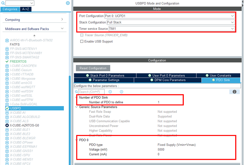
In the ''Middleware'' section, enable ''USBPD'' with the following configuration: | In the ''Middleware'' section, enable ''USBPD'' with the following configuration: | ||
*Port | *Port configuration: '''Port 0: UCPD1''' | ||
*Stack | *Stack configuration: '''PD3 Full Stack''' | ||
*Timer service | *Timer service source: '''TIM1''' | ||
Under the ''PDO | Under the ''PDO Sink'' tab is the PDO description | ||
*Number of Sink PDOs for port 0: '''1''' | *Number of Sink PDOs for port 0: '''1''' | ||
*Port 0 Sink PDO | *Port 0 Sink PDO 0 is '''5V''' | ||
[[File: | [[File:STM32StepByStep_20 SP Sink PDO Def.png|frame|center]]<br> | ||
===Configure ADC peripheral=== | |||
For the Power Delivery stack to work, VBUS needs to be monitored. To do it, an ADC needs to be configured to measure the VBUS voltage and current.<br> | |||
As the X-NUCLEO-SNK1M1 BSP is used here, the ADC configuration is not needed in CubeMX. <br> | |||
As the ADC HAL drivers are needed for it to work properly, it is still necessary to configure the ADC in CubeMX for it to include the driver files, but the actual configuration and init function are not called in this project.<br> | |||
<br> | |||
In the ''Analog'' section, enable ''ADC1'' peripheral channel 0. Leave the configuration as default, as the software pack reconfigures it.<br> | |||
[[File:USBPD_0-ADC1Conf.png|frame|center]]<br> | |||
===Enable the software pack=== | |||
In the middleware and software pack category, select the X-CUBE-TCPP software pack. Enable the 'Source' application, the 'tcpp01' board part, and the 'X-NUCLEO-SNK1M1' board support. | |||
[[File:STM32StepByStep_07 SP Enable SNK.png|frame|center]]<br> | |||
===Configure the clocks=== | |||
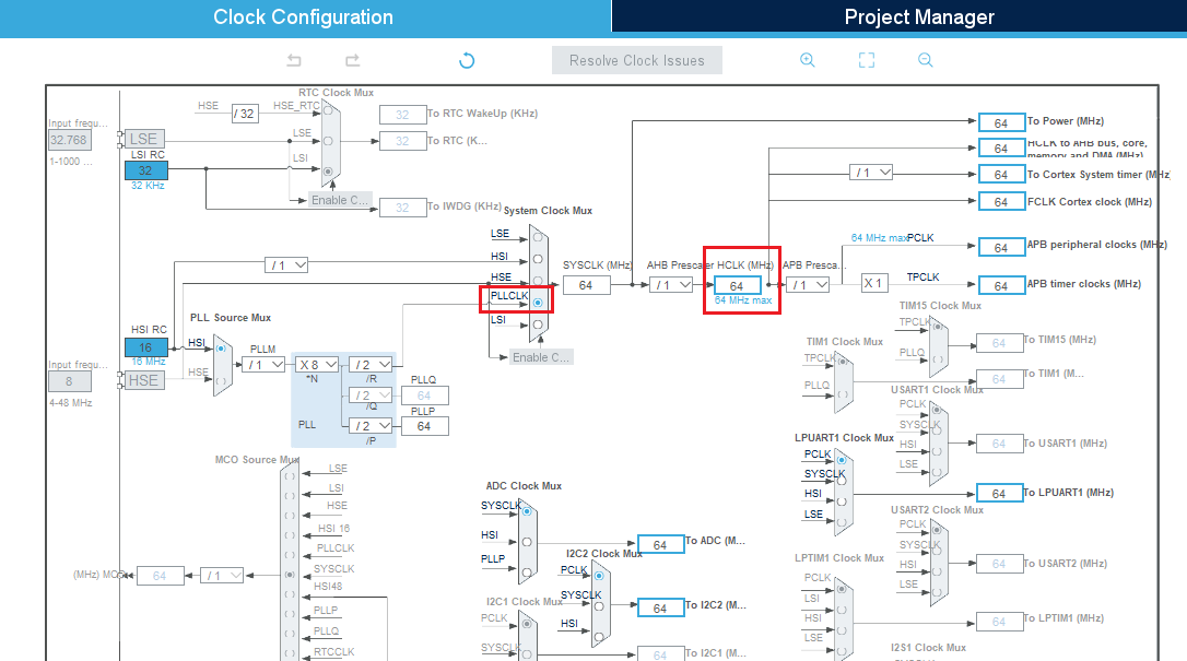
Under the ''Clock Configuration'' main tab, change the system clock mux to ''PLLCLK''. It sets the ''HCLK'' clock to 64 MHz. | |||
== | |||
Under the ''Clock Configuration'' main tab, change system clock mux to ''PLLCLK''. It sets the ''HCLK'' clock to 64 MHz. | |||
[[File:0-Clock.png|frame|center]]<br> | [[File:0-Clock.png|frame|center]]<br> | ||
| Line 143: | Line 118: | ||
}} | }} | ||
==[OPTIONAL] Configure Tracer for debug== | ===[OPTIONAL] Configure Tracer for debug=== | ||
===Configure LPUART=== | ====Configure LPUART==== | ||
On the STM32G0 Nucleo-64 board, the Virtual COM port connected to the ST-LINK is the LPUART1.<br> | On the STM32G0 Nucleo-64 board, the Virtual COM port connected to the ST-LINK is the LPUART1.<br> | ||
{{Warning|The default STM32CubeMX pins used by LPUART1 must be changed to match the STM32G0 Nucleo-64 hardware: <br> | {{Warning|The default STM32CubeMX pins used by LPUART1 must be changed to match the STM32G0 Nucleo-64 hardware: <br> | ||
*'''PA2 for TX'''<br> | *'''PA2 for TX'''<br> | ||
*'''PA3 for RX''' | *'''PA3 for RX'''}} | ||
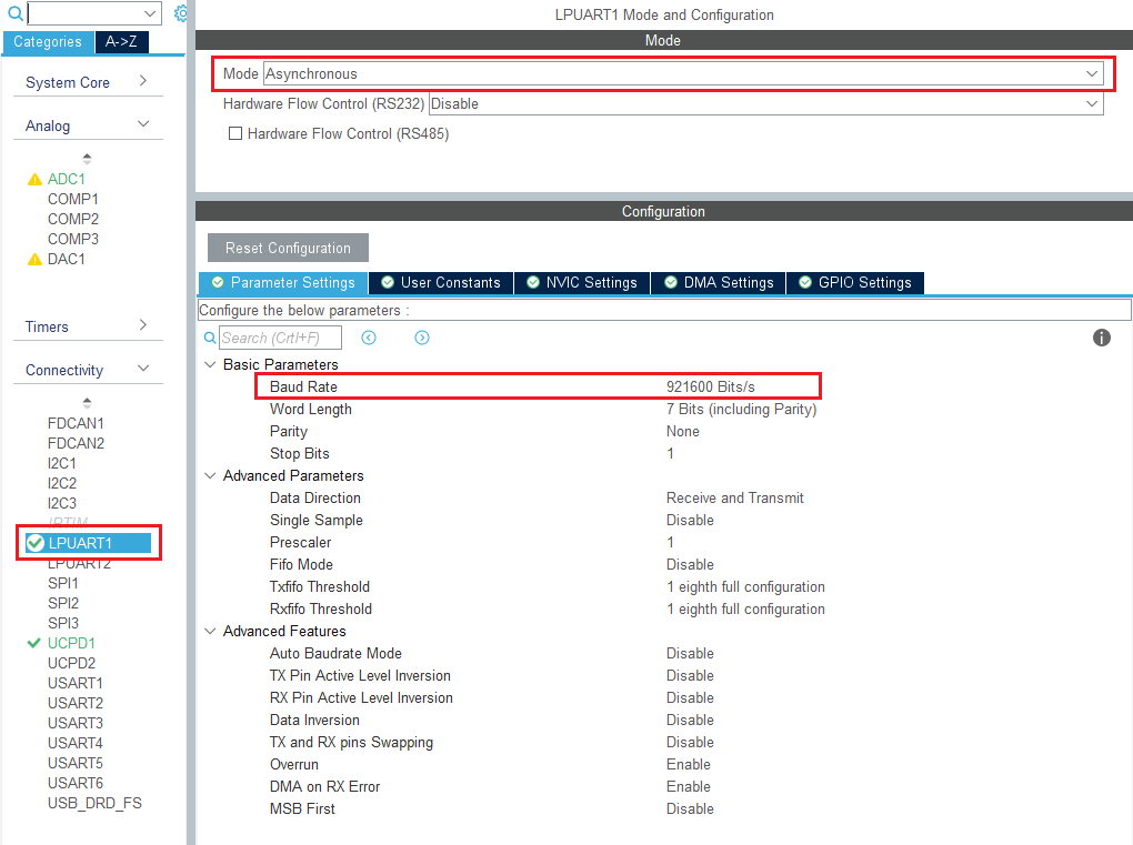
In the ''Connectivity'' section, enable ''LPUART1'' in | In the ''Connectivity'' section, enable ''LPUART1'' in asynchronous mode, and baud rate to '''921600 bauds'''. Leave the rest as default.<br> | ||
[[File:0-LPUARTConf.png|frame|center]]<br> | [[File:0-LPUARTConf.png|frame|center]]<br> | ||
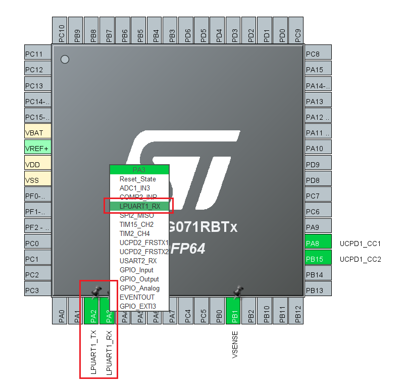
In the pinout view, left-click PA2 and PA3 to remap them to ''LPUART1_TX'' and ''LPUART1_RX''. | In the pinout view, left-click PA2 and PA3 to remap them to ''LPUART1_TX'' and ''LPUART1_RX''. | ||
| Line 160: | Line 135: | ||
[[File:2-LPUARTConf.png|frame|center]]<br> | [[File:2-LPUARTConf.png|frame|center]]<br> | ||
===Configure embedded tracer=== | ====Configure embedded tracer==== | ||
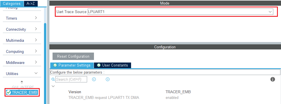
In the ''Utilities'' section, select ''TRACER_EMB'' and use ''LPUART1'' as the trace source. | In the ''Utilities'' section, select ''TRACER_EMB'' and use ''LPUART1'' as the trace source. | ||
[[File:0-tracerConf.png|frame|center]]<br> | [[File:0-tracerConf.png|frame|center]]<br> | ||
| Line 167: | Line 142: | ||
[[File:1-tracerConf.png|frame|center]]<br> | [[File:1-tracerConf.png|frame|center]]<br> | ||
===Configure UCPD monitor firmware responder for debug=== | ====Configure UCPD monitor firmware responder for debug==== | ||
The firmware interactive stack responder can be activated if interaction with the USB-PD stack is needed, using the UCPD monitor tool. | The firmware interactive stack responder can be activated if interaction with the USB-PD stack is needed, using the UCPD monitor tool. | ||
[https://www.st.com/en/development-tools/stm32cubemonucpd.html STM32CubeMonUCPD]. | [https://www.st.com/en/development-tools/stm32cubemonucpd.html STM32CubeMonUCPD]. | ||
| Line 174: | Line 149: | ||
[[File:snk0-GUIConf.png|frame|center]]<br> | [[File:snk0-GUIConf.png|frame|center]]<br> | ||
=Configure project= | ==Configure the project== | ||
[[File:Clock.png|40px|middle]] 5min<br><br> | [[File:Clock.png|40px|middle]] 5min<br><br> | ||
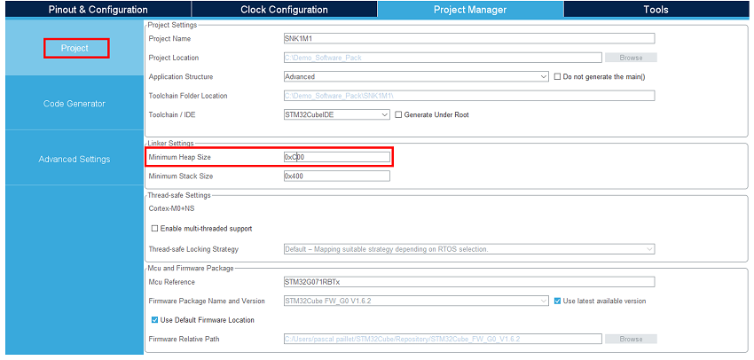
Under the ''Project Manager'' main tab, configure the minimum stack size to '''0xC00''' under the ''Project'' tab. This is a first value, which can be tuned later, depending on application needs. | Under the ''Project Manager'' main tab, configure the minimum stack size to '''0xC00''' under the ''Project'' tab. This is a first value, which can be tuned later, depending on application needs. | ||
[[File: | [[File:STM32StepByStep_08 Config Proj SNK.png|center]]<br> | ||
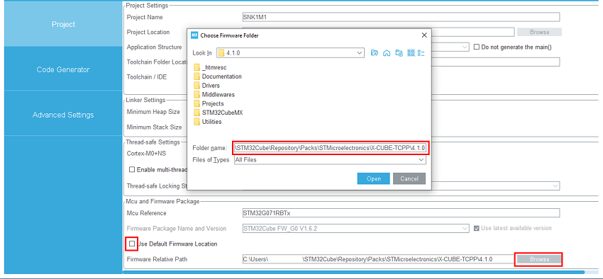
For STM32G0 or G4 MCU, uncheck “Use default firmware location” and instead, select the Software pack “c:|\user\ … \STM32Cube\Repositoryctronics/Packs\STMicroelectronics\X-CUBE-TCPP\V4.1.0\” as the firmware location to be sure to use the latest USBPD lib releases, as the standard evolution is very fast. | |||
[[File:STM32StepByStep_08 Config Proj2 SNK.png|center]]<rb> | |||
<br> | <br> | ||
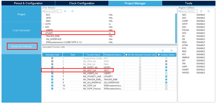
Under the ''Advanced Settings'' tab, change the LPUART driver to LL. | Under the ''Advanced Settings'' tab, change the LPUART driver to LL to save a bit of memory heap size. As ADC initialization functions are not needed (handled by the BSP drivers), uncheck ''Generate Code'' for the MX_ADC1_Init functions. | ||
[[File: | [[File:STM32StepByStep_09 Advanced SNK.png|center]]<br> | ||
=Generate code= | ==Generate the code== | ||
[[File:Clock.png|40px|middle]] 5min<br><br> | [[File:Clock.png|40px|middle]] 5min<br><br> | ||
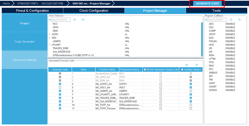
Save your file with Ctrl+ | Save your file with Ctrl+s and select generate code. | ||
[[File: | [[File:STM32StepByStep_10 Generate SNK.png|center]]<br> | ||
A warning appears, informing that a proper HAL time base is not defined. It is safer to use a dedicated timer as a HAL time base source.<br> | A warning appears, informing that a proper HAL time base is not defined. It is safer to use a dedicated timer as a HAL time base source.<br> | ||
| Line 192: | Line 169: | ||
[[File:1-projGen.png|frame|center]]<br> | [[File:1-projGen.png|frame|center]]<br> | ||
{{Info|This becomes the recommended standard way of working in the forthcoming firmware package deliveries, especially when using CMSIS OS V2, which defines Systick as FreeRTOS™ time base.<br> | {{Info|This becomes the recommended standard way of working in the forthcoming firmware package deliveries, especially when using CMSIS OS V2, which defines Systick as FreeRTOS™ time base.<br> | ||
For this demonstration, the warning can be ignored by clicking Yes.}}<br> | For this demonstration, the warning can be ignored by clicking Yes.}}.<br> | ||
==Configure the shield's jumpers== | |||
Place jumpers on the X-NUCLEO-SNK1M1 shield as shown in the picture. | |||
[[File:NewShield.PNG|frame|center]]<br> | |||
==Compile and run the application== | |||
The compilation must be performed without error or warnings.<br> | |||
Build the application by clicking on the [[File:Built_Button.png|20px|middle]] button (or select ''Project/Build Project'').<br> | |||
Run the application by clicking on the [[File:DownloadRun_Button.png|20px|middle]] button (or select ''Run/Run'').<br> | |||
==Establish the first explicit contract== | |||
[[File:Clock.png|40px|middle]] 5min<br><br> | |||
With your application running on the board, launch the STM32CubeMonitor-UCPD application. | |||
The user's board must appear in the list when clicking "Refresh list of connected boards". Double click on the | |||
corresponding line (or click "NEXT"). | |||
[[File:snkCubeMon1.png|frame|center]]<br> | |||
''Note: The ComPort may be different. It depends on the number of boards installed on the computer.'' | |||
Double click on the desired UCPD port, here Port 0, or select it and click "NEXT". | |||
[[File:snkCubeMon2.png|frame|center]]<br> | |||
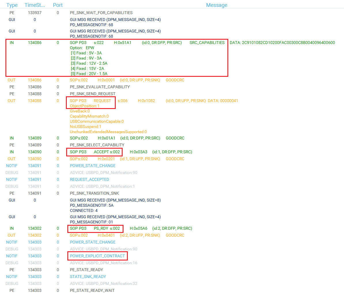
Click on the ''TRACES'' button in the bottom right corner to get protocol traces. You can then plug a power delivery source into the USB Type-C® receptacle of the X-NUCLEO-SKN1M1 shield. The screen may look like this: | |||
[[File:snkCubeMon3.png|frame|center]]<br> | |||
The figure above shows the communication between the STM32G0 and the power delivery source on the right panel. It is | |||
possible to verify the correct sequence to reach an explicit contract: | |||
# The '''capabilities''' are '''sent''' by the '''source''' (IN green message). | |||
# The '''request''' is sent by the '''STM32G0''' (OUT orange message). | |||
#The '''ACCEPT''' and the '''PS_RDY''' are sent by the '''source''' (IN green message). | |||
# The contract negotiation ends by the '''POWER_EXPLICIT_CONTRACT''' notification (blue message). | |||
For more details on how to use this tool, refer to [https://www.st.com/resource/en/user_manual/dm00536366-stm32cubemonitorucpd-software-tool-for-usb-typec-power-delivery-port-management-stmicroelectronics.pdf UM2468]. | |||
And for more details on the protocol, refer to [https://www.st.com/resource/en/user_manual/dm00598101-managing-usb-power-delivery-systems-with-stm32-microcontrollers-stmicroelectronics.pdf UM2552]. | |||
Note that this trace is very helpful for debugging and application development. | |||
=Simple USB-PD application= | <!--==Simple USB-PD application== | ||
[[File:Clock.png|40px|middle]] 10min<br><br> | [[File:Clock.png|40px|middle]] 10min<br><br> | ||
Now that the peripherals are initialized by STM32CubeMX, some minimum level of the application needs to be added: | Now that the peripherals are initialized by STM32CubeMX, some minimum level of the application needs to be added: | ||
| Line 204: | Line 213: | ||
*TCPP01‑M12 dead battery pin needs to be disabled and GPIO driven HIGH to see the source Rp, or the jumper must be set on the shield. | *TCPP01‑M12 dead battery pin needs to be disabled and GPIO driven HIGH to see the source Rp, or the jumper must be set on the shield. | ||
{{Warning | This application is a '''very basic example''' that requests the '''first default 5V PDO'''. If you want to request a '''specific voltage''' from a source, some '''user code''' that matches the sink and source PDO needs to be added. Please refer to [[STM32StepByStep:STM32_Advance_USB-Power_Delivery_Sink#-5BOPTIONAL-5D_Advanced_USB-PD_application|Advanced USB-PD application]] section after completing this basic example for a more complete application.}} | {{Warning | This application is a '''very basic example''' that requests the '''first default 5V PDO'''. If you want to request a '''specific voltage''' from a source, some '''user code''' that matches the sink and source PDO needs to be added. Please refer to [[STM32StepByStep:STM32_Advance_USB-Power_Delivery_Sink#-5BOPTIONAL-5D_Advanced_USB-PD_application|Advanced USB-PD application]] section after completing this basic example for a more complete application.}}--> | ||
== | ==Information focus : Code inserted by the software pack== | ||
By enabling the software pack in [[#Enable the software pack|section 3.7]], the code below has been added automatically in the following files: | |||
{| role="presentation" class="wikitable mw-collapsible mw-collapsed" | |||
| <strong>usbpd_dpm_user_h</strong> | |||
|- | |||
|'''<u>Between the ''/* USER CODE BEGIN-END Typedef */'' tags:</u>''' | |||
<syntaxhighlight lang="c" class="noscroll"> | <syntaxhighlight lang="c" class="noscroll"> | ||
/* | #if !defined(USBPD_REV_MAJOR) | ||
#define USBPD_REV_MAJOR (3U) /* USBPD Specification revision major */ | |||
#define USBPD_REV_MINOR (1U) /* USBPD Specification revision minor */ | |||
/* | #define USBPD_VERSION_MAJOR (1U) /* USBPD Specification version major */ | ||
#define USBPD_VERSION_MINOR (7U) /* USBPD Specification version minor */ | |||
#endif /* !USBPD_REV_MAJOR */ | |||
/** @brief USBPD PDO Selection method enum definition | |||
* | |||
*/ | |||
typedef enum | |||
{ | |||
PDO_SEL_METHOD_MAX_PWR, | |||
PDO_SEL_METHOD_MIN_PWR, | |||
PDO_SEL_METHOD_MAX_VOLT, | |||
PDO_SEL_METHOD_MIN_VOLT, | |||
PDO_SEL_METHOD_MAX_CUR, | |||
PDO_SEL_METHOD_MIN_CUR | |||
} USBPD_DPM_PDO_SelectionMethodTypeDef; | |||
/** | |||
* @brief USBPD DPM handle Structure definition | |||
* @{ | |||
*/ | |||
typedef struct | |||
{ | |||
uint32_t DPM_ListOfRcvSNKPDO[USBPD_MAX_NB_PDO]; /*!< The list of received Sink Power Data Objects from Port partner (when Port partner is a Sink or a DRP port). */ | |||
uint32_t DPM_NumberOfRcvSNKPDO; /*!< The number of received Sink Power Data Objects from port Partner (when Port partner is a Sink or a DRP port). */ | |||
uint32_t DPM_ListOfRcvSRCPDO[USBPD_MAX_NB_PDO]; /*!< The list of received Source Power Data Objects from Port partner */ | |||
uint32_t DPM_NumberOfRcvSRCPDO; /*!< The number of received Source Power Data Objects from port Partner (when Port partner is a Source or a DRP port). */ | |||
uint32_t DPM_RcvRequestDOMsg; /*!< Received request Power Data Object message from the port Partner */ | |||
uint32_t DPM_RequestDOMsgPrevious; /*!< Previous Request Power Data Object message to be sent */ | |||
USBPD_PPSSDB_TypeDef DPM_RcvPPSStatus; /*!< PPS Status received by port partner */ | |||
USBPD_SKEDB_TypeDef DPM_RcvSNKExtendedCapa; /*!< SNK Extended Capability received by port partner */ | |||
uint32_t DPM_RequestDOMsg; /*!< Request Power Data Object message to be sent */ | |||
uint32_t DPM_RDOPosition; /*!< RDO Position of requested DO in Source list of capabilities */ | |||
uint32_t DPM_RDOPositionPrevious; /*!< RDO Position of previous requested DO in Source list of capabilities */ | |||
uint32_t DPM_RequestedVoltage; /*!< Value of requested voltage */ | |||
uint32_t DPM_RequestedCurrent; /*!< Value of requested current */ | |||
} USBPD_HandleTypeDef; | |||
</syntaxhighlight> | </syntaxhighlight> | ||
{ | <br> | ||
'''<u>Between the ''/* USER CODE BEGIN-END Define */'' tags:</u>''' | |||
<syntaxhighlight lang="c" class="noscroll"> | |||
#define DPM_NO_SRC_PDO_FOUND 0xFFU /*!< No match found between Received SRC PDO and SNK capabilities */ | |||
</syntaxhighlight> | |||
|} | |||
{| role="presentation" class="wikitable mw-collapsible mw-collapsed" | |||
| <strong>usbpd_dpm_user_c</strong> | |||
|- | |||
|'''<u>Between the ''/* USER CODE BEGIN-END Includes */'' tags:</u>''' | |||
<syntaxhighlight lang="c" class="noscroll"> | |||
#if !defined(_TRACE) | |||
#include "string.h" | |||
#endif /* !_TRACE */ | |||
</syntaxhighlight> | |||
'''<u>Between the ''/* USER CODE BEGIN-END Typedef */'' tags:</u>''' | |||
<syntaxhighlight lang="c" class="noscroll"> | |||
/** @brief Sink Request characteritics Structure definition | |||
* | |||
*/ | |||
typedef struct | |||
{ | |||
uint32_t RequestedVoltageInmVunits; /*!< Sink request operating voltage in mV units */ | |||
uint32_t MaxOperatingCurrentInmAunits; /*!< Sink request Max operating current in mA units */ | |||
uint32_t OperatingCurrentInmAunits; /*!< Sink request operating current in mA units */ | |||
uint32_t MaxOperatingPowerInmWunits; /*!< Sink request Max operating power in mW units */ | |||
uint32_t OperatingPowerInmWunits; /*!< Sink request operating power in mW units */ | |||
} USBPD_DPM_SNKPowerRequestDetails_TypeDef; | |||
</syntaxhighlight> | |||
'''<u>Between the ''/* USER CODE BEGIN-END Variables */'' tags:</u>''' | |||
<syntaxhighlight lang="c" class="noscroll"> | |||
/* Method used to find the "best" PDO */ | |||
USBPD_DPM_PDO_SelectionMethodTypeDef USBPD_DPM_PDO_Sel_Method = PDO_SEL_METHOD_MAX_PWR; | |||
USBPD_HandleTypeDef DPM_Ports[USBPD_PORT_COUNT]; | |||
</syntaxhighlight> | |||
'''<u>Between the ''/* USER CODE BEGIN-END Prototypes */'' tags:</u>''' | |||
<syntaxhighlight lang="c" class="noscroll"> | |||
static void DPM_SNK_BuildRDOfromSelectedPDO(uint8_t PortNum, uint8_t IndexSrcPDO, USBPD_DPM_SNKPowerRequestDetails_TypeDef* PtrRequestPowerDetails, | |||
USBPD_SNKRDO_TypeDef* Rdo, USBPD_CORE_PDO_Type_TypeDef *PtrPowerObject); | |||
static uint32_t DPM_FindVoltageIndex(uint32_t PortNum, USBPD_DPM_SNKPowerRequestDetails_TypeDef* PtrRequestPowerDetails, uint8_t Method); | |||
</syntaxhighlight> | |||
'''<u>Between the ''/* USER CODE BEGIN-END USBPD_DPM_GetDataInfo */'' tags:</u>''' | |||
<syntaxhighlight lang="c" class="noscroll"> | <syntaxhighlight lang="c" class="noscroll"> | ||
case USBPD_CORE_DATATYPE_SNK_PDO: /*!< Handling of port Sink PDO, requested by get sink capa*/ | case USBPD_CORE_DATATYPE_SNK_PDO: /*!< Handling of port Sink PDO, requested by get sink capa*/ | ||
USBPD_PWR_IF_GetPortPDOs(PortNum, DataId, Ptr, Size); | USBPD_PWR_IF_GetPortPDOs(PortNum, DataId, Ptr, Size); | ||
*Size *= 4; | *Size *= 4; | ||
break; | break; | ||
case USBPD_CORE_DATATYPE_REQ_VOLTAGE: /*!< Get voltage value requested for BIST tests, expect 5V*/ | |||
*Size = 4; | |||
(void)memcpy((uint8_t*)Ptr, (uint8_t *)&DPM_Ports[PortNum].DPM_RequestedVoltage, *Size); | |||
break; | |||
case USBPD_CORE_REVISION: | |||
{ | |||
*Size = sizeof(USBPD_RevisionDO_TypeDef); | |||
USBPD_RevisionDO_TypeDef rev = | |||
{ | |||
/* Hardcoded values, user should use a global USBPD_RevisionDO_TypeDef variable */ | |||
.b.Revision_major = USBPD_REV_MAJOR, /*!< Major revision */ | |||
.b.Revision_minor = USBPD_REV_MINOR, /*!< Minor revision */ | |||
.b.Version_major = USBPD_VERSION_MAJOR, /*!< Major version */ | |||
.b.Version_minor = USBPD_VERSION_MINOR /*!< Minor version */ | |||
}; | |||
memcpy((uint8_t *)Ptr, &rev, *Size); | |||
break; | |||
} | |||
#if defined (USBPD_CORE_SNK_EXTENDED_CAPA) | |||
case USBPD_CORE_SNK_EXTENDED_CAPA : | |||
{ | |||
*Size = sizeof(USBPD_SKEDB_TypeDef); | |||
memcpy((uint8_t*)Ptr, (uint8_t *)&DPM_USER_Settings[PortNum].DPM_SNKExtendedCapa, *Size); | |||
} | |||
break; | |||
#endif /* USBPD_CORE_SNK_EXTENDED_CAPA */ | |||
default: | |||
break; | |||
</syntaxhighlight> | </syntaxhighlight> | ||
'''<u>Between the ''/* USER CODE BEGIN-END USBPD_DPM_SetDataInfo */'' tags:</u>''' | |||
<syntaxhighlight lang="c" class="noscroll"> | |||
case USBPD_CORE_DATATYPE_RCV_REQ_PDO : /*!< Storage of Received Sink Request PDO value */ | |||
if (Size == 4) | |||
{ | |||
memcpy((uint8_t *)&DPM_Ports[PortNum].DPM_RcvRequestDOMsg, Ptr, 4); | |||
} | |||
break; | |||
/* Case Received Source PDO values Data information : */ | |||
case USBPD_CORE_DATATYPE_RCV_SRC_PDO : | |||
if (Size <= (USBPD_MAX_NB_PDO * 4)) | |||
{ | |||
uint8_t* rdo; | |||
DPM_Ports[PortNum].DPM_NumberOfRcvSRCPDO = (Size / 4); | |||
/* Copy PDO data in DPM Handle field */ | |||
for (uint32_t index = 0; index < (Size / 4); index++) | |||
{ | |||
rdo = (uint8_t*)&DPM_Ports[PortNum].DPM_ListOfRcvSRCPDO[index]; | |||
(void)memcpy(rdo, (Ptr + (index * 4u)), (4u * sizeof(uint8_t))); | |||
} | |||
} | |||
break; | |||
case USBPD_CORE_PPS_STATUS : | |||
{ | |||
uint8_t* ext_capa; | |||
ext_capa = (uint8_t*)&DPM_Ports[PortNum].DPM_RcvPPSStatus; | |||
memcpy(ext_capa, Ptr, Size); | |||
} | |||
case USBPD_CORE_REVISION: | |||
{ | |||
/* Does nothing: User have to implement a global revision variable */ | |||
USBPD_RevisionDO_TypeDef rev = {0}; | |||
memcpy((uint8_t *)&rev, Ptr, sizeof(USBPD_RevisionDO_TypeDef)); | |||
break; | |||
} | |||
#if defined(USBPDCORE_SNK_CAPA_EXT) | |||
case USBPD_CORE_SNK_EXTENDED_CAPA : | |||
{ | |||
uint8_t* _snk_ext_capa; | |||
_snk_ext_capa = (uint8_t*)&DPM_Ports[PortNum].DPM_RcvSNKExtendedCapa; | |||
memcpy(_snk_ext_capa, Ptr, Size); | |||
} | |||
#endif /* USBPDCORE_SNK_CAPA_EXT */ | |||
default: | |||
break; | |||
</syntaxhighlight> | |||
'''<u>Between the ''/* USER CODE BEGIN-END USBPD_DPM_SNK_EvaluateCapabilities */'' tags:</u>''' | |||
<syntaxhighlight lang="c" class="noscroll"> | <syntaxhighlight lang="c" class="noscroll"> | ||
/* | USBPD_PDO_TypeDef fixed_pdo; | ||
USBPD_SNKRDO_TypeDef rdo; | |||
/* Initialize RDO */ | USBPD_HandleTypeDef *pdhandle = &DPM_Ports[PortNum]; | ||
rdo.d32 = 0; | USBPD_USER_SettingsTypeDef *puser = (USBPD_USER_SettingsTypeDef *)&DPM_USER_Settings[PortNum]; | ||
/* | USBPD_DPM_SNKPowerRequestDetails_TypeDef snkpowerrequestdetails; | ||
rdo.FixedVariableRDO.ObjectPosition = 1; | uint32_t pdoindex, size; | ||
rdo.FixedVariableRDO.OperatingCurrentIn10mAunits = | uint32_t snkpdolist[USBPD_MAX_NB_PDO]; | ||
rdo.FixedVariableRDO.MaxOperatingCurrent10mAunits = | USBPD_PDO_TypeDef snk_fixed_pdo; | ||
rdo.FixedVariableRDO.CapabilityMismatch = | |||
*PtrPowerObjectType = USBPD_CORE_PDO_TYPE_FIXED; | snkpowerrequestdetails.RequestedVoltageInmVunits = 0; | ||
*PtrRequestData = rdo.d32; | snkpowerrequestdetails.OperatingCurrentInmAunits = 0; | ||
/* USBPD_DPM_EvaluateCapabilities: Port Partner Requests Max Voltage */ | |||
/* Find the Pdo index for the requested voltage */ | |||
pdoindex = DPM_FindVoltageIndex(PortNum, &snkpowerrequestdetails, USBPD_DPM_PDO_Sel_Method); | |||
/* Initialize RDO */ | |||
rdo.d32 = 0; | |||
/* If no valid SNK PDO or if no SRC PDO match found (index>=nb of valid received SRC PDOs or function returned DPM_NO_SRC_PDO_FOUND*/ | |||
if (pdoindex >= pdhandle->DPM_NumberOfRcvSRCPDO) | |||
{ | |||
#if defined(_TRACE) | |||
USBPD_TRACE_Add(USBPD_TRACE_DEBUG, PortNum, 0, (uint8_t *) "PE_EvaluateCapability: could not find desired voltage", sizeof("PE_EvaluateCapability: could not find desired voltage")); | |||
#endif /* _TRACE */ | |||
fixed_pdo.d32 = pdhandle->DPM_ListOfRcvSRCPDO[0]; | |||
/* Read SNK PDO list for retrieving useful data to fill in RDO */ | |||
USBPD_PWR_IF_GetPortPDOs(PortNum, USBPD_CORE_DATATYPE_SNK_PDO, (uint8_t*)&snkpdolist[0], &size); | |||
/* Store value of 1st SNK PDO (Fixed) in local variable */ | |||
snk_fixed_pdo.d32 = snkpdolist[0]; | |||
rdo.FixedVariableRDO.ObjectPosition = 1; | |||
rdo.FixedVariableRDO.OperatingCurrentIn10mAunits = fixed_pdo.SRCFixedPDO.MaxCurrentIn10mAunits; | |||
rdo.FixedVariableRDO.MaxOperatingCurrent10mAunits = fixed_pdo.SRCFixedPDO.MaxCurrentIn10mAunits; | |||
rdo.FixedVariableRDO.CapabilityMismatch = 1; | |||
rdo.FixedVariableRDO.USBCommunicationsCapable = snk_fixed_pdo.SNKFixedPDO.USBCommunicationsCapable; | |||
DPM_Ports[PortNum].DPM_RequestedCurrent = puser->DPM_SNKRequestedPower.MaxOperatingCurrentInmAunits; | |||
pdhandle->DPM_RequestDOMsg = rdo.d32; | |||
*PtrPowerObjectType = USBPD_CORE_PDO_TYPE_FIXED; | |||
*PtrRequestData = rdo.d32; | |||
pdhandle->DPM_RequestedVoltage = 5000; | |||
return; | |||
} | |||
DPM_SNK_BuildRDOfromSelectedPDO(PortNum, pdoindex, &snkpowerrequestdetails,&rdo, PtrPowerObjectType); | |||
*PtrRequestData = pdhandle->DPM_RequestDOMsg; | |||
</syntaxhighlight> | </syntaxhighlight> | ||
'''<u>Between the ''/* USER CODE BEGIN-END USBPD_DPM_RequestMessageRequest */'' tags:</u>''' | |||
<syntaxhighlight lang="c" class="noscroll"> | <syntaxhighlight lang="c" class="noscroll"> | ||
/* | /* To be adapted to call the PE function */ | ||
/* _status = USBPD_PE_Send_Request(PortNum, rdo.d32, pdo_object);*/ | |||
/* USER CODE END | uint32_t voltage, allowablepower; | ||
USBPD_SNKRDO_TypeDef rdo; | |||
USBPD_PDO_TypeDef pdo; | |||
USBPD_CORE_PDO_Type_TypeDef pdo_object; | |||
USBPD_USER_SettingsTypeDef *puser = (USBPD_USER_SettingsTypeDef *)&DPM_USER_Settings[PortNum]; | |||
USBPD_DPM_SNKPowerRequestDetails_TypeDef request_details; | |||
rdo.d32 = 0; | |||
/* selected SRC PDO */ | |||
pdo.d32 = DPM_Ports[PortNum].DPM_ListOfRcvSRCPDO[(IndexSrcPDO - 1)]; | |||
voltage = RequestedVoltage; | |||
allowablepower = (puser->DPM_SNKRequestedPower.MaxOperatingCurrentInmAunits * RequestedVoltage) / 1000U; | |||
if (USBPD_TRUE == USBPD_DPM_SNK_EvaluateMatchWithSRCPDO(PortNum, pdo.d32, &voltage, &allowablepower)) | |||
{ | |||
/* Check that voltage has been correctly selected */ | |||
if (RequestedVoltage == voltage) | |||
{ | |||
request_details.RequestedVoltageInmVunits = RequestedVoltage; | |||
request_details.OperatingCurrentInmAunits = (1000U * allowablepower)/RequestedVoltage; | |||
request_details.MaxOperatingCurrentInmAunits = puser->DPM_SNKRequestedPower.MaxOperatingCurrentInmAunits; | |||
request_details.MaxOperatingPowerInmWunits = puser->DPM_SNKRequestedPower.MaxOperatingPowerInmWunits; | |||
request_details.OperatingPowerInmWunits = puser->DPM_SNKRequestedPower.OperatingPowerInmWunits; | |||
DPM_SNK_BuildRDOfromSelectedPDO(PortNum, (IndexSrcPDO - 1), &request_details, &rdo, &pdo_object); | |||
_status = USBPD_PE_Send_Request(PortNum, rdo.d32, pdo_object); | |||
} | |||
} | |||
/* USER CODE END USBPD_DPM_RequestMessageRequest */ | |||
return _status; | |||
</syntaxhighlight> | </syntaxhighlight> | ||
'''<u>Between the ''/* USER CODE BEGIN-END USBPD_USER_PRIVATE_FUNCTIONS */'' tags:</u>''' | |||
<syntaxhighlight lang="c" class="noscroll"> | <syntaxhighlight lang="c" class="noscroll"> | ||
/* | /** | ||
* @brief Examinate a given SRC PDO to check if matching with SNK capabilities. | |||
* @param PortNum Port number | |||
if (( | * @param SrcPDO Selected SRC PDO (32 bits) | ||
* @param PtrRequestedVoltage Pointer on Voltage value that could be reached if SRC PDO is requested (only valid if USBPD_TRUE is returned) in mV | |||
* @param PtrRequestedPower Pointer on Power value that could be reached if SRC PDO is requested (only valid if USBPD_TRUE is returned) in mW | |||
* @retval USBPD_FALSE of USBPD_TRUE (USBPD_TRUE returned in SRC PDO is considered matching with SNK profile) | |||
*/ | |||
uint32_t USBPD_DPM_SNK_EvaluateMatchWithSRCPDO(uint8_t PortNum, uint32_t SrcPDO, uint32_t* PtrRequestedVoltage, uint32_t* PtrRequestedPower) | |||
{ | { | ||
USBPD_PDO_TypeDef srcpdo, snkpdo; | |||
* | uint32_t match = USBPD_FALSE; | ||
uint32_t nbsnkpdo; | |||
uint32_t snkpdo_array[USBPD_MAX_NB_PDO]; | |||
uint16_t i, srcvoltage50mv, srcmaxvoltage50mv, srcminvoltage50mv, srcmaxcurrent10ma; | |||
uint16_t snkvoltage50mv, snkmaxvoltage50mv, snkminvoltage50mv, snkopcurrent10ma; | |||
uint32_t maxrequestedpower, currentrequestedpower; | |||
uint32_t maxrequestedvoltage, currentrequestedvoltage; | |||
uint32_t snkoppower250mw, srcmaxpower250mw; | |||
/* Retrieve SNK PDO list from PWR_IF storage : PDO values + nb of u32 written by PWR_IF (nb of PDOs) */ | |||
USBPD_PWR_IF_GetPortPDOs(PortNum, USBPD_CORE_DATATYPE_SNK_PDO, (uint8_t*)snkpdo_array, &nbsnkpdo); | |||
if (0 == nbsnkpdo) | |||
{ | |||
return(USBPD_FALSE); | |||
} | |||
/* Set default output values */ | |||
maxrequestedpower = 0; | |||
maxrequestedvoltage = 0; | |||
/* Check SRC PDO value according to its type */ | |||
srcpdo.d32 = SrcPDO; | |||
switch(srcpdo.GenericPDO.PowerObject) | |||
{ | |||
/* SRC Fixed Supply PDO */ | |||
case USBPD_CORE_PDO_TYPE_FIXED: | |||
srcvoltage50mv = srcpdo.SRCFixedPDO.VoltageIn50mVunits; | |||
srcmaxcurrent10ma = srcpdo.SRCFixedPDO.MaxCurrentIn10mAunits; | |||
/* Loop through SNK PDO list */ | |||
for (i=0; i<nbsnkpdo; i++) | |||
{ | |||
currentrequestedpower = 0; | |||
currentrequestedvoltage = 0; | |||
/* Retrieve SNK PDO value according to its type */ | |||
snkpdo.d32 = snkpdo_array[i]; | |||
switch(snkpdo.GenericPDO.PowerObject) | |||
{ | |||
/* SNK Fixed Supply PDO */ | |||
case USBPD_CORE_PDO_TYPE_FIXED: | |||
{ | |||
snkvoltage50mv = snkpdo.SNKFixedPDO.VoltageIn50mVunits; | |||
snkopcurrent10ma = snkpdo.SNKFixedPDO.OperationalCurrentIn10mAunits; | |||
/* Match if : | |||
SNK Voltage = SRC Voltage | |||
&& | |||
SNK Op Current <= SRC Max Current | |||
Requested Voltage : SNK Voltage | |||
Requested Op Current : SNK Op Current | |||
Requested Max Current : SNK Op Current | |||
*/ | |||
if ( (snkvoltage50mv == srcvoltage50mv) | |||
&&(snkopcurrent10ma <= srcmaxcurrent10ma)) | |||
{ | |||
currentrequestedpower = (snkvoltage50mv * snkopcurrent10ma) / 2; /* to get value in mw */ | |||
currentrequestedvoltage = snkvoltage50mv; | |||
} | |||
break; | |||
} | |||
/* SNK Variable Supply (non-battery) PDO */ | |||
case USBPD_CORE_PDO_TYPE_VARIABLE: | |||
snkmaxvoltage50mv = snkpdo.SNKVariablePDO.MaxVoltageIn50mVunits; | |||
snkminvoltage50mv = snkpdo.SNKVariablePDO.MinVoltageIn50mVunits; | |||
snkopcurrent10ma = snkpdo.SNKVariablePDO.OperationalCurrentIn10mAunits; | |||
/* Match if : | |||
SNK Max voltage >= SRC Voltage | |||
&& | |||
SNK Min voltage <= SRC Voltage | |||
&& | |||
SNK Op current <= SRC Max current | |||
Requested Voltage : SRC Voltage | |||
Requested Op Current : SNK Op Current | |||
Requested Max Current : SNK Op Current | |||
*/ | |||
if ( (snkmaxvoltage50mv >= srcvoltage50mv) | |||
&&(snkminvoltage50mv <= srcvoltage50mv) | |||
&&(snkopcurrent10ma <= srcmaxcurrent10ma)) | |||
{ | |||
currentrequestedpower = (srcvoltage50mv * snkopcurrent10ma) / 2; /* to get value in mw */ | |||
currentrequestedvoltage = srcvoltage50mv; | |||
} | |||
break; | |||
/* SNK Battery Supply PDO */ | |||
case USBPD_CORE_PDO_TYPE_BATTERY: | |||
snkmaxvoltage50mv = snkpdo.SNKBatteryPDO.MaxVoltageIn50mVunits; | |||
snkminvoltage50mv = snkpdo.SNKBatteryPDO.MinVoltageIn50mVunits; | |||
snkoppower250mw = snkpdo.SNKBatteryPDO.OperationalPowerIn250mWunits; | |||
/* Match if : | |||
SNK Max voltage >= SRC Voltage | |||
&& | |||
SNK Min voltage <= SRC Voltage | |||
&& | |||
SNK Op power <= SRC Max current * SRC Voltage | |||
Requested Voltage : SRC Voltage | |||
Requested Op Current : SNK Op Power/ SRC Voltage | |||
Requested Max Current : SNK Op Power/ SRC Voltage | |||
*/ | |||
if ( (snkmaxvoltage50mv >= srcvoltage50mv) | |||
&&(snkminvoltage50mv <= srcvoltage50mv) | |||
&&(snkoppower250mw <= ((srcvoltage50mv * srcmaxcurrent10ma)/500))) /* to get value in 250 mw units */ | |||
{ | |||
currentrequestedvoltage = srcvoltage50mv; | |||
currentrequestedpower = snkoppower250mw; | |||
} | |||
break; | |||
/* SNK Augmented Power Data Object (APDO) */ | |||
case USBPD_CORE_PDO_TYPE_APDO: | |||
break; | |||
default: | |||
break; | |||
} | |||
if (currentrequestedpower > maxrequestedpower) | |||
{ | |||
match = USBPD_TRUE; | |||
maxrequestedpower = currentrequestedpower; | |||
maxrequestedvoltage = currentrequestedvoltage; | |||
} | |||
} | |||
break; | |||
/* SRC Variable Supply (non-battery) PDO */ | |||
case USBPD_CORE_PDO_TYPE_VARIABLE: | |||
srcmaxvoltage50mv = srcpdo.SRCVariablePDO.MaxVoltageIn50mVunits; | |||
srcminvoltage50mv = srcpdo.SRCVariablePDO.MinVoltageIn50mVunits; | |||
srcmaxcurrent10ma = srcpdo.SRCVariablePDO.MaxCurrentIn10mAunits; | |||
/* Loop through SNK PDO list */ | |||
for (i=0; i<nbsnkpdo; i++) | |||
{ | |||
currentrequestedpower = 0; | |||
currentrequestedvoltage = 0; | |||
/* Retrieve SNK PDO value according to its type */ | |||
snkpdo.d32 = snkpdo_array[i]; | |||
switch(snkpdo.GenericPDO.PowerObject) | |||
{ | |||
/* SNK Fixed Supply PDO */ | |||
case USBPD_CORE_PDO_TYPE_FIXED: | |||
/* No match */ | |||
break; | |||
/* SNK Variable Supply (non-battery) PDO */ | |||
case USBPD_CORE_PDO_TYPE_VARIABLE: | |||
snkmaxvoltage50mv = snkpdo.SNKVariablePDO.MaxVoltageIn50mVunits; | |||
snkminvoltage50mv = snkpdo.SNKVariablePDO.MinVoltageIn50mVunits; | |||
snkopcurrent10ma = snkpdo.SNKVariablePDO.OperationalCurrentIn10mAunits; | |||
/* Match if : | |||
SNK Max voltage >= SRC Max Voltage | |||
&& | |||
SNK Min voltage <= SRC Min Voltage | |||
&& | |||
SNK Op current <= SRC Max current | |||
Requested Voltage : Any value between SRC Min Voltage and SRC Max Voltage | |||
Requested Op Current : SNK Op Current | |||
Requested Max Current : SNK Op Current | |||
*/ | |||
if ( (snkmaxvoltage50mv >= srcmaxvoltage50mv) | |||
&&(snkminvoltage50mv <= srcminvoltage50mv) | |||
&&(snkopcurrent10ma <= srcmaxcurrent10ma)) | |||
{ | |||
currentrequestedpower = (srcmaxvoltage50mv * snkopcurrent10ma) / 2; /* to get value in mw */ | |||
currentrequestedvoltage = srcmaxvoltage50mv; | |||
} | |||
break; | |||
/* SNK Battery Supply PDO */ | |||
case USBPD_CORE_PDO_TYPE_BATTERY: | |||
snkmaxvoltage50mv = snkpdo.SNKBatteryPDO.MaxVoltageIn50mVunits; | |||
snkminvoltage50mv = snkpdo.SNKBatteryPDO.MinVoltageIn50mVunits; | |||
snkoppower250mw = snkpdo.SNKBatteryPDO.OperationalPowerIn250mWunits; | |||
/* Match if : | |||
SNK Max voltage >= SRC Max Voltage | |||
&& | |||
SNK Min voltage <= SRC Min Voltage | |||
&& | |||
SNK Op power <= SRC Max current * SRC Max Voltage | |||
Requested Voltage : Any value between SRC Min Voltage and SRC Max Voltage, that fulfill | |||
SNK Op power <= Voltage * SRC Max Current | |||
Requested Op Current : SNK Op Power/ SRC Voltage | |||
Requested Max Current : SNK Op Power/ SRC Voltage | |||
*/ | |||
if ( (snkmaxvoltage50mv >= srcmaxvoltage50mv) | |||
&&(snkminvoltage50mv <= srcminvoltage50mv) | |||
&&(snkoppower250mw <= ((srcmaxvoltage50mv * srcmaxcurrent10ma)/500))) /* to get value in 250 mw units */ | |||
{ | |||
currentrequestedpower = snkoppower250mw * 250; /* to get value in mw */ | |||
currentrequestedvoltage = srcmaxvoltage50mv; | |||
} | |||
break; | |||
/* SNK Augmented Power Data Object (APDO) */ | |||
case USBPD_CORE_PDO_TYPE_APDO: | |||
break; | |||
default: | |||
break; | |||
} | |||
if (currentrequestedpower > maxrequestedpower) | |||
{ | |||
match = USBPD_TRUE; | |||
maxrequestedpower = currentrequestedpower; | |||
maxrequestedvoltage = currentrequestedvoltage; | |||
} | |||
} | |||
break; | |||
/* SRC Battery Supply PDO */ | |||
case USBPD_CORE_PDO_TYPE_BATTERY: | |||
srcmaxvoltage50mv = srcpdo.SRCBatteryPDO.MaxVoltageIn50mVunits; | |||
srcminvoltage50mv = srcpdo.SRCBatteryPDO.MinVoltageIn50mVunits; | |||
srcmaxpower250mw = srcpdo.SRCBatteryPDO.MaxAllowablePowerIn250mWunits; | |||
/* Loop through SNK PDO list */ | |||
for (i=0; i<nbsnkpdo; i++) | |||
{ | |||
currentrequestedpower = 0; | |||
currentrequestedvoltage = 0; | |||
/* Retrieve SNK PDO value according to its type */ | |||
snkpdo.d32 = snkpdo_array[i]; | |||
switch(snkpdo.GenericPDO.PowerObject) | |||
{ | |||
/* SNK Fixed Supply PDO */ | |||
case USBPD_CORE_PDO_TYPE_FIXED: | |||
/* No match */ | |||
break; | |||
/* SNK Variable Supply (non-battery) PDO */ | |||
case USBPD_CORE_PDO_TYPE_VARIABLE: | |||
snkmaxvoltage50mv = snkpdo.SNKVariablePDO.MaxVoltageIn50mVunits; | |||
snkminvoltage50mv = snkpdo.SNKVariablePDO.MinVoltageIn50mVunits; | |||
snkopcurrent10ma = snkpdo.SNKVariablePDO.OperationalCurrentIn10mAunits; | |||
/* Match if : | |||
SNK Max voltage >= SRC Max Voltage | |||
&& | |||
SNK Min voltage <= SRC Min Voltage | |||
&& | |||
SNK Op current * SRC Max Voltage <= SRC Max Power | |||
Requested Voltage : Any value between SRC Min Voltage and SRC Max Voltage : SRC Max Voltage | |||
Requested Op Current : SNK Op Current | |||
Requested Max Current : SNK Op Current | |||
*/ | |||
if ( (snkmaxvoltage50mv >= srcmaxvoltage50mv) | |||
&&(snkminvoltage50mv <= srcminvoltage50mv) | |||
&&(srcmaxvoltage50mv * snkopcurrent10ma <= srcmaxpower250mw)) | |||
{ | |||
currentrequestedpower = (srcmaxvoltage50mv * snkopcurrent10ma) / 2; /* to get value in mw */ | |||
currentrequestedvoltage = srcmaxvoltage50mv; | |||
} | |||
break; | |||
/* SNK Battery Supply PDO */ | |||
case USBPD_CORE_PDO_TYPE_BATTERY: | |||
snkmaxvoltage50mv = snkpdo.SNKBatteryPDO.MaxVoltageIn50mVunits; | |||
snkminvoltage50mv = snkpdo.SNKBatteryPDO.MinVoltageIn50mVunits; | |||
snkoppower250mw = snkpdo.SNKBatteryPDO.OperationalPowerIn250mWunits; | |||
/* Match if : | |||
SNK Max voltage >= SRC Max Voltage | |||
&& | |||
SNK Min voltage <= SRC Min Voltage | |||
&& | |||
SNK Op power <= SRC Max power | |||
Requested Voltage : Any value between SRC Min Voltage and SRC Max Voltage, that fulfill | |||
SNK Op power <= Voltage * SRC Max Current | |||
Requested Op Current : SNK Op Power/ SRC Voltage | |||
Requested Max Current : SNK Op Power/ SRC Voltage | |||
*/ | |||
if ( (snkmaxvoltage50mv >= srcmaxvoltage50mv) | |||
&&(snkminvoltage50mv <= srcminvoltage50mv) | |||
&&(snkoppower250mw <= srcmaxpower250mw)) | |||
{ | |||
currentrequestedpower = snkoppower250mw * 250; /* to get value in mw */ | |||
currentrequestedvoltage = srcmaxvoltage50mv; | |||
} | |||
break; | |||
/* SNK Augmented Power Data Object (APDO) */ | |||
case USBPD_CORE_PDO_TYPE_APDO: | |||
break; | |||
default: | |||
break; | |||
} | |||
if (currentrequestedpower > maxrequestedpower) | |||
{ | |||
match = USBPD_TRUE; | |||
maxrequestedpower = currentrequestedpower; | |||
maxrequestedvoltage = currentrequestedvoltage; | |||
} | |||
} | |||
break; | |||
/* Augmented Power Data Object (APDO) */ | |||
case USBPD_CORE_PDO_TYPE_APDO: | |||
{ | |||
uint16_t srcmaxvoltage100mv, srcmaxcurrent50ma; | |||
srcmaxvoltage100mv = srcpdo.SRCSNKAPDO.MaxVoltageIn100mV; | |||
srcmaxcurrent50ma = srcpdo.SRCSNKAPDO.MaxCurrentIn50mAunits; | |||
/* Loop through SNK PDO list */ | |||
for (i=0; i<nbsnkpdo; i++) | |||
{ | |||
currentrequestedpower = 0; | |||
currentrequestedvoltage = 0; | |||
/* Retrieve SNK PDO value according to its type */ | |||
snkpdo.d32 = snkpdo_array[i]; | |||
switch(snkpdo.GenericPDO.PowerObject) | |||
{ | |||
case USBPD_CORE_PDO_TYPE_FIXED: | |||
case USBPD_CORE_PDO_TYPE_VARIABLE: | |||
case USBPD_CORE_PDO_TYPE_BATTERY: | |||
/* No match */ | |||
break; | |||
/* SNK Augmented Power Data Object (APDO) */ | |||
case USBPD_CORE_PDO_TYPE_APDO: | |||
{ | |||
uint16_t snkmaxvoltage100mv, snkminvoltage100mv, snkmaxcurrent50ma; | |||
snkminvoltage100mv = snkpdo.SRCSNKAPDO.MinVoltageIn100mV; | |||
snkmaxvoltage100mv = snkpdo.SRCSNKAPDO.MaxVoltageIn100mV; | |||
snkmaxcurrent50ma = snkpdo.SRCSNKAPDO.MaxCurrentIn50mAunits; | |||
/* Match if voltage matches with the APDO voltage range */ | |||
if ((PWR_DECODE_100MV(snkminvoltage100mv) <= (*PtrRequestedVoltage)) | |||
&& ((*PtrRequestedVoltage) <= PWR_DECODE_100MV(snkmaxvoltage100mv)) | |||
&& (snkmaxcurrent50ma <= srcmaxcurrent50ma)) | |||
{ | |||
if (0 != *PtrRequestedPower) | |||
{ | |||
currentrequestedpower = (*PtrRequestedVoltage * PWR_DECODE_50MA(snkmaxcurrent50ma)) / 1000; /* to get value in mw */ | |||
currentrequestedvoltage = (*PtrRequestedVoltage / 50); | |||
} | |||
else | |||
{ | |||
*PtrRequestedVoltage = MIN(PWR_DECODE_100MV(srcmaxvoltage100mv), PWR_DECODE_100MV(snkmaxvoltage100mv)); | |||
currentrequestedpower = (*PtrRequestedVoltage * PWR_DECODE_50MA(snkmaxcurrent50ma)) / 1000; /* to get value in mw */ | |||
currentrequestedvoltage = (*PtrRequestedVoltage / 50); | |||
} | |||
} | |||
} | |||
break; | |||
default: | |||
break; | |||
} | |||
if (currentrequestedpower > maxrequestedpower) | |||
{ | |||
match = USBPD_TRUE; | |||
maxrequestedpower = currentrequestedpower; | |||
maxrequestedvoltage = currentrequestedvoltage; | |||
} | |||
} | |||
} | |||
break; | |||
default: | |||
return(USBPD_FALSE); | |||
} | |||
if (maxrequestedpower > 0) | |||
{ | |||
*PtrRequestedPower = maxrequestedpower; | |||
*PtrRequestedVoltage = maxrequestedvoltage * 50; /* value in mV */ | |||
} | |||
return(match); | |||
} | } | ||
/** | |||
* @brief Find PDO index that offers the most amount of power and in accordance with SNK capabilities. | |||
* @param PortNum Port number | |||
* @param PtrRequestPowerDetails Sink requested power details structure pointer | |||
* @retval Index of PDO within source capabilities message (DPM_NO_SRC_PDO_FOUND indicating not found) | |||
*/ | |||
static uint32_t DPM_FindVoltageIndex(uint32_t PortNum, USBPD_DPM_SNKPowerRequestDetails_TypeDef* PtrRequestPowerDetails, uint8_t Method) | |||
{ | { | ||
uint32_t | uint32_t *ptpdoarray; | ||
USBPD_PDO_TypeDef pdo; | |||
uint32_t voltage; | |||
uint32_t reqvoltage; | |||
/* | uint32_t nbpdo; | ||
uint32_t allowablepower; | |||
uint32_t selpower; | |||
uint32_t allowablecurrent; | |||
* | uint32_t selcurrent; | ||
uint32_t curr_index = DPM_NO_SRC_PDO_FOUND; | |||
uint32_t temp_index; | |||
/* | USBPD_USER_SettingsTypeDef *puser = (USBPD_USER_SettingsTypeDef *)&DPM_USER_Settings[PortNum]; | ||
allowablepower = 0; | |||
selpower = 0; | |||
reqvoltage = 0; | |||
voltage = 0; | |||
selcurrent = 0; | |||
/* Search PDO index among Source PDO of Port */ | |||
nbpdo = DPM_Ports[PortNum].DPM_NumberOfRcvSRCPDO; | |||
ptpdoarray = DPM_Ports[PortNum].DPM_ListOfRcvSRCPDO; | |||
/* search the best PDO in the list of source PDOs */ | |||
for (temp_index = 0; temp_index < nbpdo; temp_index++) | |||
{ | |||
pdo.d32 = ptpdoarray[temp_index]; | |||
/* Check if the received source PDO is matching any of the SNK PDO */ | |||
allowablepower = 0; | |||
if (USBPD_TRUE == USBPD_DPM_SNK_EvaluateMatchWithSRCPDO(PortNum, pdo.d32, &voltage, &allowablepower)) | |||
{ | |||
allowablecurrent = (allowablepower / voltage) * 1000U; | |||
/* Choose the best PDO depending on the user preferences */ | |||
switch (Method) | |||
{ | |||
case PDO_SEL_METHOD_MAX_PWR: | |||
if (allowablepower > selpower) | |||
{ | |||
/* Consider the current PDO the best one until now */ | |||
curr_index = temp_index; | |||
selpower = allowablepower; | |||
reqvoltage = voltage; | |||
selcurrent = allowablecurrent; | |||
} | |||
break; | |||
case PDO_SEL_METHOD_MIN_PWR: | |||
if ((allowablepower < selpower) || (selpower == 0)) | |||
{ | |||
/* Consider the current PDO the best one until now */ | |||
curr_index = temp_index; | |||
selpower = allowablepower; | |||
reqvoltage = voltage; | |||
selcurrent = allowablecurrent; | |||
} | |||
break; | |||
case PDO_SEL_METHOD_MAX_VOLT: | |||
if (voltage > reqvoltage) | |||
{ | |||
/* Consider the current PDO the best one until now */ | |||
curr_index = temp_index; | |||
selpower = allowablepower; | |||
reqvoltage = voltage; | |||
selcurrent = allowablecurrent; | |||
} | |||
break; | |||
= | case PDO_SEL_METHOD_MIN_VOLT: | ||
if ((voltage < reqvoltage) || (reqvoltage == 0)) | |||
{ | |||
/* Consider the current PDO the best one until now */ | |||
curr_index = temp_index; | |||
selpower = allowablepower; | |||
reqvoltage = voltage; | |||
selcurrent = allowablecurrent; | |||
} | |||
break; | |||
case PDO_SEL_METHOD_MAX_CUR: | |||
if (allowablecurrent > selcurrent) | |||
{ | |||
/* Consider the current PDO the best one until now */ | |||
curr_index = temp_index; | |||
selpower = allowablepower; | |||
reqvoltage = voltage; | |||
selcurrent = allowablecurrent; | |||
} | |||
break; | |||
case PDO_SEL_METHOD_MIN_CUR: | |||
if ((allowablecurrent < selcurrent) || (selcurrent == 0)) | |||
{ | |||
/* Consider the current PDO the best one until now */ | |||
curr_index = temp_index; | |||
selpower = allowablepower; | |||
reqvoltage = voltage; | |||
selcurrent = allowablecurrent; | |||
} | |||
break; | |||
default: | |||
/* Default behavior: last PDO is selected */ | |||
curr_index = temp_index; | |||
selpower = allowablepower; | |||
reqvoltage = voltage; | |||
selcurrent = allowablecurrent; | |||
} | |||
} | |||
} | |||
= | /* If a suitable PDO was found */ | ||
{ | if (curr_index != DPM_NO_SRC_PDO_FOUND) | ||
{ | |||
/* Fill the request power details */ | |||
PtrRequestPowerDetails->MaxOperatingCurrentInmAunits = puser->DPM_SNKRequestedPower.MaxOperatingCurrentInmAunits; | |||
PtrRequestPowerDetails->OperatingCurrentInmAunits = (1000U * selpower) / reqvoltage; | |||
PtrRequestPowerDetails->MaxOperatingPowerInmWunits = puser->DPM_SNKRequestedPower.MaxOperatingPowerInmWunits; | |||
PtrRequestPowerDetails->OperatingPowerInmWunits = selpower; | |||
PtrRequestPowerDetails->RequestedVoltageInmVunits = reqvoltage; | |||
} | |||
return curr_index; | |||
} | |||
/** | |||
* | * @brief Build RDO to be used in Request message according to selected PDO from received SRC Capabilities | ||
* | * @param PortNum Port number | ||
* @param IndexSrcPDO Index on the selected SRC PDO (value between 0 to 6) | |||
* @param PtrRequestPowerDetails Sink requested power details structure pointer | |||
* @param Rdo Pointer on the RDO | |||
* @param PtrPowerObject Pointer on the selected power object | |||
* @retval None | |||
*/ | |||
void DPM_SNK_BuildRDOfromSelectedPDO(uint8_t PortNum, uint8_t IndexSrcPDO, | |||
USBPD_DPM_SNKPowerRequestDetails_TypeDef *PtrRequestPowerDetails, | |||
USBPD_SNKRDO_TypeDef* Rdo, USBPD_CORE_PDO_Type_TypeDef *PtrPowerObject) | |||
{ | |||
uint32_t mv = 0, mw = 0, ma = 0, size; | |||
USBPD_PDO_TypeDef pdo; | |||
USBPD_SNKRDO_TypeDef rdo; | |||
USBPD_HandleTypeDef *pdhandle = &DPM_Ports[PortNum]; | |||
USBPD_USER_SettingsTypeDef *puser = (USBPD_USER_SettingsTypeDef *)&DPM_USER_Settings[PortNum]; | |||
uint32_t snkpdolist[USBPD_MAX_NB_PDO]; | |||
USBPD_PDO_TypeDef snk_fixed_pdo; | |||
/* Initialize RDO */ | |||
rdo.d32 = 0; | |||
/* Read SNK PDO list for retrieving useful data to fill in RDO */ | |||
USBPD_PWR_IF_GetPortPDOs(PortNum, USBPD_CORE_DATATYPE_SNK_PDO, (uint8_t*)&snkpdolist[0], &size); | |||
/* Store value of 1st SNK PDO (Fixed) in local variable */ | |||
snk_fixed_pdo.d32 = snkpdolist[0]; | |||
/* Set common fields in RDO */ | |||
pdo.d32 = pdhandle->DPM_ListOfRcvSRCPDO[0]; | |||
rdo.GenericRDO.USBCommunicationsCapable = snk_fixed_pdo.SNKFixedPDO.USBCommunicationsCapable; | |||
if (USBPD_SPECIFICATION_REV2 < DPM_Params[PortNum].PE_SpecRevision) | |||
{ | |||
rdo.FixedVariableRDO.UnchunkedExtendedMessage = DPM_Settings[PortNum].PE_PD3_Support.d.PE_UnchunkSupport; | |||
DPM_Params[PortNum].PE_UnchunkSupport = USBPD_FALSE; | |||
/* Set unchuncked bit if supported by port partner;*/ | |||
if (USBPD_TRUE == pdo.SRCFixedPDO.UnchunkedExtendedMessage) | |||
{ | |||
DPM_Params[PortNum].PE_UnchunkSupport = USBPD_TRUE; | |||
} | |||
} | |||
/* If no valid SNK PDO or if no SRC PDO match found (index>=nb of valid received SRC PDOs */ | |||
if ((size < 1) || (IndexSrcPDO >= pdhandle->DPM_NumberOfRcvSRCPDO)) | |||
{ | |||
/* USBPD_DPM_EvaluateCapabilities: Mismatch, could not find desired pdo index */ | |||
#ifdef _TRACE | |||
USBPD_TRACE_Add(USBPD_TRACE_DEBUG, PortNum, 0, (uint8_t *)"DPM_SNK_BuildRDOfromSelectedPDO: Pb in SRC PDO selection", | |||
sizeof("DPM_SNK_BuildRDOfromSelectedPDO: Pb in SRC PDO selection")); | |||
#endif /* _TRACE */ | |||
rdo.FixedVariableRDO.ObjectPosition = 1; | |||
rdo.FixedVariableRDO.OperatingCurrentIn10mAunits = pdo.SRCFixedPDO.MaxCurrentIn10mAunits; | |||
rdo.FixedVariableRDO.MaxOperatingCurrent10mAunits = pdo.SRCFixedPDO.MaxCurrentIn10mAunits; | |||
rdo.FixedVariableRDO.CapabilityMismatch = 1; | |||
rdo.FixedVariableRDO.USBCommunicationsCapable = snk_fixed_pdo.SNKFixedPDO.USBCommunicationsCapable; | |||
DPM_Ports[PortNum].DPM_RequestedCurrent = puser->DPM_SNKRequestedPower.MaxOperatingCurrentInmAunits; | |||
/* USBPD_DPM_EvaluateCapabilities: Mismatch, could not find desired pdo index */ | |||
pdhandle->DPM_RequestDOMsg = rdo.d32; | |||
return; | |||
} | |||
/* Set the Object position */ | |||
rdo.GenericRDO.ObjectPosition = IndexSrcPDO + 1; | |||
rdo.GenericRDO.NoUSBSuspend = 0; | |||
/* Extract power information from Power Data Object */ | |||
pdo.d32 = pdhandle->DPM_ListOfRcvSRCPDO[IndexSrcPDO]; | |||
*PtrPowerObject = pdo.GenericPDO.PowerObject; | |||
/* Retrieve request details from SRC PDO selection */ | |||
mv = PtrRequestPowerDetails->RequestedVoltageInmVunits; | |||
ma = PtrRequestPowerDetails->OperatingCurrentInmAunits; | |||
switch(pdo.GenericPDO.PowerObject) | |||
{ | |||
case USBPD_CORE_PDO_TYPE_FIXED: | |||
case USBPD_CORE_PDO_TYPE_VARIABLE: | |||
{ | |||
/* USBPD_DPM_EvaluateCapabilities: Mismatch, less power offered than the operating power */ | |||
ma = USBPD_MIN(ma, puser->DPM_SNKRequestedPower.MaxOperatingCurrentInmAunits); | |||
mw = (ma * mv)/1000; /* mW */ | |||
DPM_Ports[PortNum].DPM_RequestedCurrent = ma; | |||
rdo.FixedVariableRDO.OperatingCurrentIn10mAunits = ma / 10; | |||
rdo.FixedVariableRDO.MaxOperatingCurrent10mAunits = ma / 10; | |||
if(mw < puser->DPM_SNKRequestedPower.OperatingPowerInmWunits) | |||
{ | |||
/* USBPD_DPM_EvaluateCapabilities: Mismatch, less power offered than the operating power */ | |||
rdo.FixedVariableRDO.MaxOperatingCurrent10mAunits = puser->DPM_SNKRequestedPower.MaxOperatingCurrentInmAunits / 10; | |||
rdo.FixedVariableRDO.CapabilityMismatch = 1; | |||
} | |||
} | |||
break; | |||
case USBPD_CORE_PDO_TYPE_BATTERY: | |||
{ | |||
/* USBPD_DPM_EvaluateCapabilities: Battery Request Data Object */ | |||
mw = USBPD_MIN(PtrRequestPowerDetails->OperatingPowerInmWunits, puser->DPM_SNKRequestedPower.MaxOperatingPowerInmWunits); /* mW */ | |||
ma = (1000 * mw) / mv; /* mA */ | |||
ma = USBPD_MIN(ma, puser->DPM_SNKRequestedPower.MaxOperatingCurrentInmAunits); | |||
DPM_Ports[PortNum].DPM_RequestedCurrent = ma; | |||
mw = (ma * mv)/1000; /* mW */ | |||
rdo.BatteryRDO.OperatingPowerIn250mWunits = mw / 250; | |||
rdo.BatteryRDO.MaxOperatingPowerIn250mWunits = mw / 250; | |||
if(mw < puser->DPM_SNKRequestedPower.OperatingPowerInmWunits) | |||
{ | |||
/* Mismatch, less power offered than the operating power */ | |||
rdo.BatteryRDO.CapabilityMismatch = 1; | |||
} | |||
} | |||
break; | |||
case USBPD_CORE_PDO_TYPE_APDO: | |||
{ | |||
DPM_Ports[PortNum].DPM_RequestedCurrent = ma; | |||
rdo.ProgRDO.ObjectPosition = IndexSrcPDO + 1; | |||
rdo.ProgRDO.OperatingCurrentIn50mAunits = ma / 50; | |||
rdo.ProgRDO.OutputVoltageIn20mV = mv / 20; | |||
} | |||
break; | |||
default: | |||
break; | |||
} | |||
pdhandle->DPM_RequestDOMsg = rdo.d32; | |||
pdhandle->DPM_RDOPosition = rdo.GenericRDO.ObjectPosition; | |||
Rdo->d32 = pdhandle->DPM_RequestDOMsg; | |||
/* Get the requested voltage */ | |||
pdhandle->DPM_RequestedVoltage = mv; | |||
} | |||
</syntaxhighlight> | |||
|} | |||
== | {| role="presentation" class="wikitable mw-collapsible mw-collapsed" | ||
| <strong>usbpd_pdo_defs.h</strong> | |||
|- | |||
|'''<u>Between the ''/* USER CODE BEGIN-END Typedef */'' tags:</u>''' | |||
* | <syntaxhighlight lang="c" class="noscroll"> | ||
* | /** | ||
* | * @brief USBPD Port PDO Structure definition | ||
*/ | |||
typedef struct | |||
{ | |||
uint32_t *ListOfPDO; /*!< Pointer on Power Data Objects list, defining port capabilities */ | |||
uint8t *NumberOfPDO; /*!< Number of Power Data Objects defined in ListOfPDO | |||
This parameter must be set at max to @ref USBPD_MAX_NB_PDO value */ | |||
} USBPD_PortPDO_TypeDef; | |||
/** | |||
* @brief USBPD Port PDO Storage Structure definition | |||
*/ | |||
typedef struct | |||
{ | |||
USBPD_PortPDO_TypeDef SourcePDO; /*!< SRC Power Data Objects */ | |||
USBPD_PortPDO_TypeDef SinkPDO; /*!< SNK Power Data Objects */ | |||
} USBPD_PWR_Port_PDO_Storage_TypeDef; | |||
</syntaxhighlight> | |||
'''<u>Between the ''/* USER CODE BEGIN-END Variables */'' tags:</u>''' | |||
<syntaxhighlight lang="c" class="noscroll"> | |||
#ifndef _GUI_INTERFACE | |||
#ifndef __USBPD_PWR_IF_C | |||
extern uint8_t USBPD_NbPDO[4]; | |||
extern uint32_t PORT0_PDO_ListSRC[USBPD_MAX_NB_PDO]; | |||
extern uint32_t PORT0_PDO_ListSNK[USBPD_MAX_NB_PDO]; | |||
#else /* __USBPD_PWR_IF_C */ | |||
uint8_t USBPD_NbPDO[4] = {(PORT0_NB_SINKPDO), | |||
(PORT0_NB_SOURCEPDO)}; | |||
#endif /* __USBPD_PWR_IF_C */ | |||
#endif /* _GUI_INTERFACE */ | |||
</syntaxhighlight> | |||
|} | |||
{| role="presentation" class="wikitable mw-collapsible mw-collapsed" | |||
<syntaxhighlight> | | <strong>usbpd_pwr_if.c</strong> | ||
|- | |||
|'''<u>Between the ''/* USER CODE BEGIN-END Private_Variables */'' tags:</u>''' | |||
<syntaxhighlight lang="c" class="noscroll"> | |||
/** | |||
* @brief USBPD Port PDO Storage array declaration | |||
[ | */ | ||
USBPD_PWR_Port_PDO_Storage_TypeDef PWR_Port_PDO_Storage[USBPD_PORT_COUNT]; | |||
</syntaxhighlight> | </syntaxhighlight> | ||
'''<u>Between the ''/* USER CODE BEGIN-END USBPD_PWR_IF_Init */'' tags:</u>''' | |||
<syntaxhighlight lang="c" class="noscroll"> | <syntaxhighlight lang="c" class="noscroll"> | ||
USBPD_StatusTypeDef _status = USBPD_OK; | |||
PWR_Port_PDO_Storage[USBPD_PORT_0].SinkPDO.ListOfPDO = (uint32_t *)PORT0_PDO_ListSNK; | |||
</syntaxhighlight> | PWR_Port_PDO_Storage[USBPD_PORT_0].SinkPDO.NumberOfPDO = &USBPD_NbPDO[0]; | ||
return _status; | |||
</syntaxhighlight> | |||
'''<u>Between the ''/* USER CODE BEGIN-END USBPD_PWR_IF_GetPortPDOs */'' tags:</u>''' | |||
<syntaxhighlight lang="c" class="noscroll"> | <syntaxhighlight lang="c" class="noscroll"> | ||
if (DataId == USBPD_CORE_DATATYPE_SRC_PDO) | |||
* | { | ||
#if defined (_GUI_INTERFACE) | |||
*Size = USBPD_NbPDO[1]; | |||
memcpy(Ptr,PORT0_PDO_ListSRC, sizeof(uint32_t) * USBPD_NbPDO[1]); | |||
</syntaxhighlight> | #else | ||
*Size = PORT0_NB_SOURCEPDO; | |||
memcpy(Ptr,PORT0_PDO_ListSRC, sizeof(uint32_t) * PORT0_NB_SOURCEPDO); | |||
#endif /* _GUI_INTERFACE */ | |||
} | |||
else | |||
{ | |||
#if defined (_GUI_INTERFACE) | |||
*Size = USBPD_NbPDO[0]; | |||
memcpy(Ptr,PORT0_PDO_ListSNK, sizeof(uint32_t) * USBPD_NbPDO[0]); | |||
#else | |||
*Size = PORT0_NB_SINKPDO; | |||
memcpy(Ptr,PORT0_PDO_ListSNK, sizeof(uint32_t) * PORT0_NB_SINKPDO); | |||
#endif /* _GUI_INTERFACE */ | |||
} | |||
</syntaxhighlight> | |||
|} | |||
{| role="presentation" class="wikitable mw-collapsible mw-collapsed" | |||
<syntaxhighlight lang="c"> | | <strong>usbpd_pwr_user.c</strong> | ||
|- | |||
|'''<u>Between the ''/* USER CODE BEGIN-END Include */'' tags:</u>''' | |||
<syntaxhighlight lang="c" class="noscroll"> | |||
</syntaxhighlight> | #include "app_tcpp.h" | ||
</syntaxhighlight> | |||
< | '''<u>Between the ''/* USER CODE BEGIN-END BSP_USBPD_PWR_VbusGetVoltage */'' tags:</u>''' | ||
''' | <syntaxhighlight lang="c" class="noscroll"> | ||
/* Check if instance is valid */ | |||
int32_t ret = BSP_ERROR_NONE; | |||
if ((Instance >= USBPD_PWR_INSTANCES_NBR) || (NULL == pVoltage)) | |||
{ | |||
ret = BSP_ERROR_WRONG_PARAM; | |||
*pVoltage = 0; | |||
} | |||
else | |||
{ | |||
uint32_t value; | |||
uint32_t vadc; | |||
uint32_t voltage; | |||
value = LL_ADC_REG_ReadConversionData12(ADC1); | |||
vadc = (value * VDDA_APPLI) / ADC_FULL_SCALE; | |||
voltage = vadc * (SNK1M1_VSENSE_RA + SNK1M1_VSENSE_RB ) / SNK1M1_VSENSE_RB ; | |||
*pVoltage = voltage; | |||
} | |||
return ret; | |||
</syntaxhighlight> | |||
'''<u>Between the ''/* USER CODE BEGIN-END BSP_USBPD_PWR_VbusGetCurrent */'' tags:</u>''' | |||
<syntaxhighlight lang="c" class="noscroll"> | |||
/* Check if instance is valid */ | |||
int32_t ret = BSP_ERROR_NONE; | |||
if ((Instance >= USBPD_PWR_INSTANCES_NBR) || (NULL == pCurrent)) | |||
{ | |||
ret = BSP_ERROR_WRONG_PARAM; | |||
*pCurrent = 0; | |||
} | |||
else | |||
{ | |||
*pCurrent = 0; | |||
} | |||
return ret; | |||
</syntaxhighlight> | |||
|} | |||
<br><br> | <br><br> | ||
<big>'''You can find other applicative examples on GitHub: [https://github.com/STMicroelectronics/x-cube-tcpp x-cube-tcpp]'''</big> | <big>'''You can find other applicative examples on GitHub: [https://github.com/STMicroelectronics/x-cube-tcpp x-cube-tcpp]'''</big> | ||
=References= | ==Project with a custom board== | ||
This chapter allows building an USBPD source application using a custom board with an STM32 MCU from series G0, G4, H5, L5, or U5 that includes the UCPD peripheral. | |||
{{Info|Selected resources: ADC1-IN9, PB6, and PC10, are for the example, replaced by the custom board resources affectation.}} | |||
* As in chapter 2: Create the project | |||
* As in chapter 3.1: Clear the pinout | |||
* As in chapter 3.2: Select the X-CUBE-TCPP software pack | |||
Do not select the board support for X-NUCLEO-SNK1M1, as your application is based on a custom board. | |||
[[File:STM32StepByStep_12 Custom SP Selct SNK.png|center]]<br> | |||
* As in chapter 3.3: Configure UCPD Peripheral | |||
* As in chapter 3.4: Configure FreeRTOS Middleware | |||
* As in chapter 3.5: Configure USBPD Middleware | |||
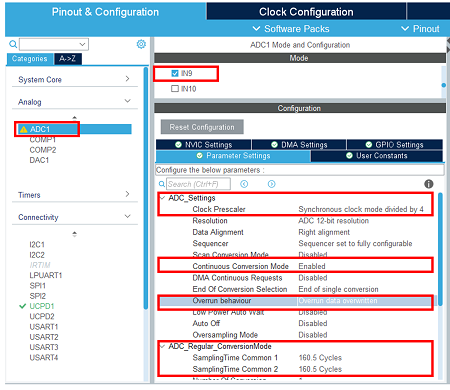
* Configure ADC Peripheral | |||
Select and configure the ADC and its channel on which Vbus is connected for monitoring. | |||
Select the ADC and its channel. | |||
Adjust the clock prescaler. | |||
Keep 12 Bits resolution. | |||
Enable the continuous conversion mode, | |||
and set a medium cycle sampling time. | |||
[[File:STM32StepByStep_13 Custom ADC SNK.png|center]]<br> | |||
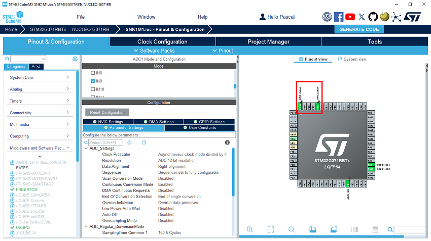
* Configure GPIO | |||
In the Pinout view, select the GPIO output for TCPP01 ''VCC'' and a second GPIO output for TCPP01 ''DB''. | |||
[[File:STM32StepByStep_14 Custom GPIO SNK.png|center]]<br> | |||
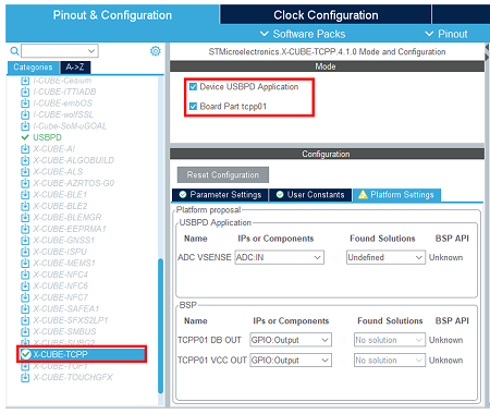
* Enable the software pack | |||
In the middleware category, select the X-CUBE-TCPP software pack and enable its application and board part. | |||
[[File:STM32StepByStep_15 Custom SP Enable SNK.png|center]]<br> | |||
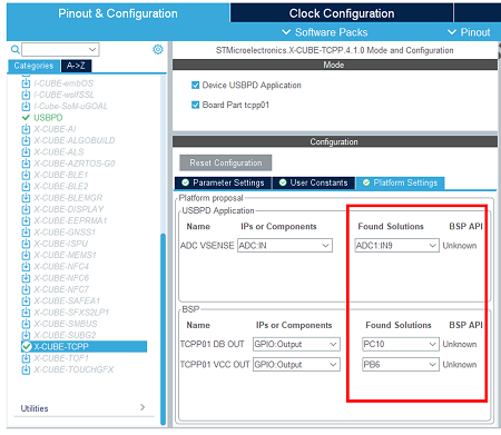
* Assign resources to the application requirements | |||
[[File:STM32StepByStep_16 Custom SP Platform SNK.png|center]]<br> | |||
<!--[[File:STM32StepByStep:18 Custom SRC SP Platform2.png|center]]<BR>--> | |||
* As in chapter 4: Configure the project | |||
However, in the Advanced settings, keep ADC initialization code generation. | |||
* As in chapter 5: Generate code | |||
* As in chapter 7: Compile and run the application | |||
==References== | |||
<references /> | <references /> | ||
<noinclude> | <noinclude> | ||
[[Category:Getting_started_with_STM32_and_USB-Power_Delivery|10]] | |||
[[Category:USB Power Delivery|15]] | [[Category:USB Power Delivery|15]] | ||
{{PublicationRequestId | 31066| 14/05/24|}} | |||
{{PublicationRequestId | | |||
{{PublicationRequestId | 21569 | 11/10/2021 | ??}} | {{PublicationRequestId | 21569 | 11/10/2021 | ??}} | ||
</noinclude> | </noinclude> | ||
Latest revision as of 15:08, 22 August 2024
Target description
This tutorial helps to:
- Use the X-NUCLEO-SNK1M1 shield that includes a TCPP01-M12 protection circuit and provides a USB Type-C® connector
- Create a USB-PD Sink device with the NUCLEO-G071RB board and the X-NUCLEO-SNK1M1 using STM32CubeMX software
Prerequisites
- Computer with Windows 7 (or higher)
- Computer with Windows 7 (or higher)
Hardware
Software
Literature
- UM2324 NUCLEO-G071RB User Manual
- UM2773 X-NUCLEO-SNK1M1 User Manual
 How to build an USBPD Sink application using the X-Cube-TCPP software pack
Create a USB-PD Sink Device
![]() Total 45min
Total 45min
1. Software pack installation
Open STM32CubeMX, in the software pack area, click on the install/remove button.
Then select the STMicroelectronics tab, scroll down to the X-Cube-TCPP software pack, and click on the install button if it is not already installed.
2. Creating the project
![]() 5min
5min
In STM32CubeMX, create a new STM32 project. As a target selection, choose the NUCLEO-G071RB from the Board Selector Tab.
Click "Start Project", then in the file menu, create a new folder under your project's name, and click "Save".
When prompted for initializing peripherals with their default mode, click No.
3. Configuring the system
At this point, your project is created. The next steps show how to configure the peripherals and options needed for the project.
3.1. Clear the pinout
To start from a blank configuration, click on the Pinout menu and select Clear Pinouts. This will reset the pinouts in the Pinout view.
3.2. Select the X-CUBE-TCPP software pack
From the software pack menu:
Select the X-CUBE-TCPP Software pack and enable its Sink application, the tcpp01 board part, and the X-NUCLEO-SNK1M1 board support.
3.3. Configure UCPD peripheral
In the Connectivity tab, select the UCPD1 peripheral and enable it in sink mode. Under the NVIC Settings tab, enable UCPD global interrupts.
Under the DMA Settings tab, add UCPD1_RX and UCPD1_TX DMA requests. Select DMA1 channel 4 for RX and DMA1 channel 2 for TX.
3.4. Configure FreeRTOS Middleware
In the Middleware section, enable FreeRTOS with CMSIS_V1 interface. Under the Config Parameters tab, change "TOTAL_HEAP_SIZE" to 7000 bytes.
3.5. Configure USBPD Middleware
In the Middleware section, enable USBPD with the following configuration:
- Port configuration: Port 0: UCPD1
- Stack configuration: PD3 Full Stack
- Timer service source: TIM1
Under the PDO Sink tab is the PDO description
- Number of Sink PDOs for port 0: 1
- Port 0 Sink PDO 0 is 5V
3.6. Configure ADC peripheral
For the Power Delivery stack to work, VBUS needs to be monitored. To do it, an ADC needs to be configured to measure the VBUS voltage and current.
As the X-NUCLEO-SNK1M1 BSP is used here, the ADC configuration is not needed in CubeMX.
As the ADC HAL drivers are needed for it to work properly, it is still necessary to configure the ADC in CubeMX for it to include the driver files, but the actual configuration and init function are not called in this project.
In the Analog section, enable ADC1 peripheral channel 0. Leave the configuration as default, as the software pack reconfigures it.
3.7. Enable the software pack
In the middleware and software pack category, select the X-CUBE-TCPP software pack. Enable the 'Source' application, the 'tcpp01' board part, and the 'X-NUCLEO-SNK1M1' board support.
3.8. Configure the clocks
Under the Clock Configuration main tab, change the system clock mux to PLLCLK. It sets the HCLK clock to 64 MHz.
3.9. [OPTIONAL] Configure Tracer for debug
3.9.1. Configure LPUART
On the STM32G0 Nucleo-64 board, the Virtual COM port connected to the ST-LINK is the LPUART1.
In the Connectivity section, enable LPUART1 in asynchronous mode, and baud rate to 921600 bauds. Leave the rest as default.
In the pinout view, left-click PA2 and PA3 to remap them to LPUART1_TX and LPUART1_RX.
Under the DMA Configuration tab, add a request for LPUART1_TX. Use DMA1 channel 3.
Finally, under the NVIC Settings tab, enable LPUART1 global interrupts.
3.9.2. Configure embedded tracer
In the Utilities section, select TRACER_EMB and use LPUART1 as the trace source.
Then, go back to the USBPD middleware configuration and check the Tracer Source checkbox.
3.9.3. Configure UCPD monitor firmware responder for debug
The firmware interactive stack responder can be activated if interaction with the USB-PD stack is needed, using the UCPD monitor tool. STM32CubeMonUCPD. GUI can be activated only with tracer. In the "Utilities" section, enable GUI_INTERFACE, then enter free text to describe the board.
4. Configure the project
![]() 5min
5min
Under the Project Manager main tab, configure the minimum stack size to 0xC00 under the Project tab. This is a first value, which can be tuned later, depending on application needs.
For STM32G0 or G4 MCU, uncheck “Use default firmware location” and instead, select the Software pack “c:|\user\ … \STM32Cube\Repositoryctronics/Packs\STMicroelectronics\X-CUBE-TCPP\V4.1.0\” as the firmware location to be sure to use the latest USBPD lib releases, as the standard evolution is very fast.
Under the Advanced Settings tab, change the LPUART driver to LL to save a bit of memory heap size. As ADC initialization functions are not needed (handled by the BSP drivers), uncheck Generate Code for the MX_ADC1_Init functions.
5. Generate the code
Save your file with Ctrl+s and select generate code.
A warning appears, informing that a proper HAL time base is not defined. It is safer to use a dedicated timer as a HAL time base source.
For this demonstration, the below warning can be ignored by clicking Yes.
.
6. Configure the shield's jumpers
Place jumpers on the X-NUCLEO-SNK1M1 shield as shown in the picture.
7. Compile and run the application
The compilation must be performed without error or warnings.
Build the application by clicking on the ![]() button (or select Project/Build Project).
button (or select Project/Build Project).
Run the application by clicking on the ![]() button (or select Run/Run).
button (or select Run/Run).
8. Establish the first explicit contract
![]() 5min
5min
With your application running on the board, launch the STM32CubeMonitor-UCPD application.
The user's board must appear in the list when clicking "Refresh list of connected boards". Double click on the
corresponding line (or click "NEXT").
Note: The ComPort may be different. It depends on the number of boards installed on the computer. Double click on the desired UCPD port, here Port 0, or select it and click "NEXT".
Click on the TRACES button in the bottom right corner to get protocol traces. You can then plug a power delivery source into the USB Type-C® receptacle of the X-NUCLEO-SKN1M1 shield. The screen may look like this:
The figure above shows the communication between the STM32G0 and the power delivery source on the right panel. It is possible to verify the correct sequence to reach an explicit contract:
- The capabilities are sent by the source (IN green message).
- The request is sent by the STM32G0 (OUT orange message).
- The ACCEPT and the PS_RDY are sent by the source (IN green message).
- The contract negotiation ends by the POWER_EXPLICIT_CONTRACT notification (blue message).
For more details on how to use this tool, refer to UM2468. And for more details on the protocol, refer to UM2552. Note that this trace is very helpful for debugging and application development.
9. Information focus : Code inserted by the software pack
By enabling the software pack in section 3.7, the code below has been added automatically in the following files:
| usbpd_dpm_user_h |
Between the /* USER CODE BEGIN-END Typedef */ tags:
#if !defined(USBPD_REV_MAJOR)
#define USBPD_REV_MAJOR      (3U)    /* USBPD Specification revision major */
#define USBPD_REV_MINOR      (1U)    /* USBPD Specification revision minor */
#define USBPD_VERSION_MAJOR  (1U)    /* USBPD Specification version major  */
#define USBPD_VERSION_MINOR  (7U)    /* USBPD Specification version minor  */
#endif /* !USBPD_REV_MAJOR */

/** @brief  USBPD PDO Selection method enum definition
  *
  */
typedef enum
{
  PDO_SEL_METHOD_MAX_PWR,
  PDO_SEL_METHOD_MIN_PWR,
  PDO_SEL_METHOD_MAX_VOLT,
  PDO_SEL_METHOD_MIN_VOLT,
  PDO_SEL_METHOD_MAX_CUR,
  PDO_SEL_METHOD_MIN_CUR
} USBPD_DPM_PDO_SelectionMethodTypeDef;

/**
  * @brief  USBPD DPM handle Structure definition
  * @{
  */
typedef struct
{
  uint32_t                      DPM_ListOfRcvSNKPDO[USBPD_MAX_NB_PDO];   /*!< The list of received Sink Power Data Objects from Port partner (when Port partner is a Sink or a DRP port). */
  uint32_t                      DPM_NumberOfRcvSNKPDO;                   /*!< The number of received Sink Power Data Objects from port Partner (when Port partner is a Sink or a DRP port). */
  uint32_t                      DPM_ListOfRcvSRCPDO[USBPD_MAX_NB_PDO];   /*!< The list of received Source Power Data Objects from Port partner     */
  uint32_t                      DPM_NumberOfRcvSRCPDO;                   /*!< The number of received Source Power Data Objects from port Partner  (when Port partner is a Source or a DRP port). */
  uint32_t                      DPM_RcvRequestDOMsg;                     /*!< Received request Power Data Object message from the port Partner     */
  uint32_t                      DPM_RequestDOMsgPrevious;                /*!< Previous Request Power Data Object message to be sent                */


  USBPD_PPSSDB_TypeDef          DPM_RcvPPSStatus;                        /*!< PPS Status received by port partner                                  */
  USBPD_SKEDB_TypeDef           DPM_RcvSNKExtendedCapa;                  /*!< SNK Extended Capability received by port partner                     */

  uint32_t                      DPM_RequestDOMsg;                        /*!< Request Power Data Object message to be sent                         */
  uint32_t                      DPM_RDOPosition;                         /*!< RDO Position of requested DO in Source list of capabilities          */
  uint32_t                      DPM_RDOPositionPrevious;                 /*!< RDO Position of previous requested DO in Source list of capabilities */
  uint32_t                      DPM_RequestedVoltage;                    /*!< Value of requested voltage                                           */
  uint32_t                      DPM_RequestedCurrent;                    /*!< Value of requested current                                           */
} USBPD_HandleTypeDef;
#define DPM_NO_SRC_PDO_FOUND 0xFFU /*!< No match found between Received SRC PDO and SNK capabilities */
|
| usbpd_dpm_user_c |
Between the /* USER CODE BEGIN-END Includes */ tags:
#if !defined(_TRACE)
#include "string.h"
#endif /* !_TRACE */
Between the /* USER CODE BEGIN-END Typedef */ tags: /** @brief Sink Request characteritics Structure definition
*
*/
typedef struct
{
uint32_t RequestedVoltageInmVunits; /*!< Sink request operating voltage in mV units */
uint32_t MaxOperatingCurrentInmAunits; /*!< Sink request Max operating current in mA units */
uint32_t OperatingCurrentInmAunits; /*!< Sink request operating current in mA units */
uint32_t MaxOperatingPowerInmWunits; /*!< Sink request Max operating power in mW units */
uint32_t OperatingPowerInmWunits; /*!< Sink request operating power in mW units */
} USBPD_DPM_SNKPowerRequestDetails_TypeDef;
Between the /* USER CODE BEGIN-END Variables */ tags: /* Method used to find the "best" PDO */
USBPD_DPM_PDO_SelectionMethodTypeDef USBPD_DPM_PDO_Sel_Method = PDO_SEL_METHOD_MAX_PWR;
USBPD_HandleTypeDef DPM_Ports[USBPD_PORT_COUNT];
Between the /* USER CODE BEGIN-END Prototypes */ tags: static void DPM_SNK_BuildRDOfromSelectedPDO(uint8_t PortNum, uint8_t IndexSrcPDO, USBPD_DPM_SNKPowerRequestDetails_TypeDef* PtrRequestPowerDetails,
USBPD_SNKRDO_TypeDef* Rdo, USBPD_CORE_PDO_Type_TypeDef *PtrPowerObject);
static uint32_t DPM_FindVoltageIndex(uint32_t PortNum, USBPD_DPM_SNKPowerRequestDetails_TypeDef* PtrRequestPowerDetails, uint8_t Method);
Between the /* USER CODE BEGIN-END USBPD_DPM_GetDataInfo */ tags: case USBPD_CORE_DATATYPE_SNK_PDO: /*!< Handling of port Sink PDO, requested by get sink capa*/
USBPD_PWR_IF_GetPortPDOs(PortNum, DataId, Ptr, Size);
*Size *= 4;
break;
case USBPD_CORE_DATATYPE_REQ_VOLTAGE: /*!< Get voltage value requested for BIST tests, expect 5V*/
*Size = 4;
(void)memcpy((uint8_t*)Ptr, (uint8_t *)&DPM_Ports[PortNum].DPM_RequestedVoltage, *Size);
break;
case USBPD_CORE_REVISION:
{
*Size = sizeof(USBPD_RevisionDO_TypeDef);
USBPD_RevisionDO_TypeDef rev =
{
/* Hardcoded values, user should use a global USBPD_RevisionDO_TypeDef variable */
.b.Revision_major = USBPD_REV_MAJOR, /*!< Major revision */
.b.Revision_minor = USBPD_REV_MINOR, /*!< Minor revision */
.b.Version_major = USBPD_VERSION_MAJOR, /*!< Major version */
.b.Version_minor = USBPD_VERSION_MINOR /*!< Minor version */
};
memcpy((uint8_t *)Ptr, &rev, *Size);
break;
}
#if defined (USBPD_CORE_SNK_EXTENDED_CAPA)
case USBPD_CORE_SNK_EXTENDED_CAPA :
{
*Size = sizeof(USBPD_SKEDB_TypeDef);
memcpy((uint8_t*)Ptr, (uint8_t *)&DPM_USER_Settings[PortNum].DPM_SNKExtendedCapa, *Size);
}
break;
#endif /* USBPD_CORE_SNK_EXTENDED_CAPA */
default:
break;
Between the /* USER CODE BEGIN-END USBPD_DPM_SetDataInfo */ tags: case USBPD_CORE_DATATYPE_RCV_REQ_PDO : /*!< Storage of Received Sink Request PDO value */
if (Size == 4)
{
memcpy((uint8_t *)&DPM_Ports[PortNum].DPM_RcvRequestDOMsg, Ptr, 4);
}
break;
/* Case Received Source PDO values Data information : */
case USBPD_CORE_DATATYPE_RCV_SRC_PDO :
if (Size <= (USBPD_MAX_NB_PDO * 4))
{
uint8_t* rdo;
DPM_Ports[PortNum].DPM_NumberOfRcvSRCPDO = (Size / 4);
/* Copy PDO data in DPM Handle field */
for (uint32_t index = 0; index < (Size / 4); index++)
{
rdo = (uint8_t*)&DPM_Ports[PortNum].DPM_ListOfRcvSRCPDO[index];
(void)memcpy(rdo, (Ptr + (index * 4u)), (4u * sizeof(uint8_t)));
}
}
break;
case USBPD_CORE_PPS_STATUS :
{
uint8_t* ext_capa;
ext_capa = (uint8_t*)&DPM_Ports[PortNum].DPM_RcvPPSStatus;
memcpy(ext_capa, Ptr, Size);
}
case USBPD_CORE_REVISION:
{
/* Does nothing: User have to implement a global revision variable */
USBPD_RevisionDO_TypeDef rev = {0};
memcpy((uint8_t *)&rev, Ptr, sizeof(USBPD_RevisionDO_TypeDef));
break;
}
#if defined(USBPDCORE_SNK_CAPA_EXT)
case USBPD_CORE_SNK_EXTENDED_CAPA :
{
uint8_t* _snk_ext_capa;
_snk_ext_capa = (uint8_t*)&DPM_Ports[PortNum].DPM_RcvSNKExtendedCapa;
memcpy(_snk_ext_capa, Ptr, Size);
}
#endif /* USBPDCORE_SNK_CAPA_EXT */
default:
break;
Between the /* USER CODE BEGIN-END USBPD_DPM_SNK_EvaluateCapabilities */ tags: USBPD_PDO_TypeDef fixed_pdo;
USBPD_SNKRDO_TypeDef rdo;
USBPD_HandleTypeDef *pdhandle = &DPM_Ports[PortNum];
USBPD_USER_SettingsTypeDef *puser = (USBPD_USER_SettingsTypeDef *)&DPM_USER_Settings[PortNum];
USBPD_DPM_SNKPowerRequestDetails_TypeDef snkpowerrequestdetails;
uint32_t pdoindex, size;
uint32_t snkpdolist[USBPD_MAX_NB_PDO];
USBPD_PDO_TypeDef snk_fixed_pdo;
snkpowerrequestdetails.RequestedVoltageInmVunits = 0;
snkpowerrequestdetails.OperatingCurrentInmAunits = 0;
/* USBPD_DPM_EvaluateCapabilities: Port Partner Requests Max Voltage */
/* Find the Pdo index for the requested voltage */
pdoindex = DPM_FindVoltageIndex(PortNum, &snkpowerrequestdetails, USBPD_DPM_PDO_Sel_Method);
/* Initialize RDO */
rdo.d32 = 0;
/* If no valid SNK PDO or if no SRC PDO match found (index>=nb of valid received SRC PDOs or function returned DPM_NO_SRC_PDO_FOUND*/
if (pdoindex >= pdhandle->DPM_NumberOfRcvSRCPDO)
{
#if defined(_TRACE)
USBPD_TRACE_Add(USBPD_TRACE_DEBUG, PortNum, 0, (uint8_t *) "PE_EvaluateCapability: could not find desired voltage", sizeof("PE_EvaluateCapability: could not find desired voltage"));
#endif /* _TRACE */
fixed_pdo.d32 = pdhandle->DPM_ListOfRcvSRCPDO[0];
/* Read SNK PDO list for retrieving useful data to fill in RDO */
USBPD_PWR_IF_GetPortPDOs(PortNum, USBPD_CORE_DATATYPE_SNK_PDO, (uint8_t*)&snkpdolist[0], &size);
/* Store value of 1st SNK PDO (Fixed) in local variable */
snk_fixed_pdo.d32 = snkpdolist[0];
rdo.FixedVariableRDO.ObjectPosition = 1;
rdo.FixedVariableRDO.OperatingCurrentIn10mAunits = fixed_pdo.SRCFixedPDO.MaxCurrentIn10mAunits;
rdo.FixedVariableRDO.MaxOperatingCurrent10mAunits = fixed_pdo.SRCFixedPDO.MaxCurrentIn10mAunits;
rdo.FixedVariableRDO.CapabilityMismatch = 1;
rdo.FixedVariableRDO.USBCommunicationsCapable = snk_fixed_pdo.SNKFixedPDO.USBCommunicationsCapable;
DPM_Ports[PortNum].DPM_RequestedCurrent = puser->DPM_SNKRequestedPower.MaxOperatingCurrentInmAunits;
pdhandle->DPM_RequestDOMsg = rdo.d32;
*PtrPowerObjectType = USBPD_CORE_PDO_TYPE_FIXED;
*PtrRequestData = rdo.d32;
pdhandle->DPM_RequestedVoltage = 5000;
return;
}
DPM_SNK_BuildRDOfromSelectedPDO(PortNum, pdoindex, &snkpowerrequestdetails,&rdo, PtrPowerObjectType);
*PtrRequestData = pdhandle->DPM_RequestDOMsg;
Between the /* USER CODE BEGIN-END USBPD_DPM_RequestMessageRequest */ tags: /* To be adapted to call the PE function */
/* _status = USBPD_PE_Send_Request(PortNum, rdo.d32, pdo_object);*/
uint32_t voltage, allowablepower;
USBPD_SNKRDO_TypeDef rdo;
USBPD_PDO_TypeDef pdo;
USBPD_CORE_PDO_Type_TypeDef pdo_object;
USBPD_USER_SettingsTypeDef *puser = (USBPD_USER_SettingsTypeDef *)&DPM_USER_Settings[PortNum];
USBPD_DPM_SNKPowerRequestDetails_TypeDef request_details;
rdo.d32 = 0;
/* selected SRC PDO */
pdo.d32 = DPM_Ports[PortNum].DPM_ListOfRcvSRCPDO[(IndexSrcPDO - 1)];
voltage = RequestedVoltage;
allowablepower = (puser->DPM_SNKRequestedPower.MaxOperatingCurrentInmAunits * RequestedVoltage) / 1000U;
if (USBPD_TRUE == USBPD_DPM_SNK_EvaluateMatchWithSRCPDO(PortNum, pdo.d32, &voltage, &allowablepower))
{
/* Check that voltage has been correctly selected */
if (RequestedVoltage == voltage)
{
request_details.RequestedVoltageInmVunits = RequestedVoltage;
request_details.OperatingCurrentInmAunits = (1000U * allowablepower)/RequestedVoltage;
request_details.MaxOperatingCurrentInmAunits = puser->DPM_SNKRequestedPower.MaxOperatingCurrentInmAunits;
request_details.MaxOperatingPowerInmWunits = puser->DPM_SNKRequestedPower.MaxOperatingPowerInmWunits;
request_details.OperatingPowerInmWunits = puser->DPM_SNKRequestedPower.OperatingPowerInmWunits;
DPM_SNK_BuildRDOfromSelectedPDO(PortNum, (IndexSrcPDO - 1), &request_details, &rdo, &pdo_object);
_status = USBPD_PE_Send_Request(PortNum, rdo.d32, pdo_object);
}
}
/* USER CODE END USBPD_DPM_RequestMessageRequest */
return _status;
Between the /* USER CODE BEGIN-END USBPD_USER_PRIVATE_FUNCTIONS */ tags: /**
* @brief Examinate a given SRC PDO to check if matching with SNK capabilities.
* @param PortNum Port number
* @param SrcPDO Selected SRC PDO (32 bits)
* @param PtrRequestedVoltage Pointer on Voltage value that could be reached if SRC PDO is requested (only valid if USBPD_TRUE is returned) in mV
* @param PtrRequestedPower Pointer on Power value that could be reached if SRC PDO is requested (only valid if USBPD_TRUE is returned) in mW
* @retval USBPD_FALSE of USBPD_TRUE (USBPD_TRUE returned in SRC PDO is considered matching with SNK profile)
*/
uint32_t USBPD_DPM_SNK_EvaluateMatchWithSRCPDO(uint8_t PortNum, uint32_t SrcPDO, uint32_t* PtrRequestedVoltage, uint32_t* PtrRequestedPower)
{
USBPD_PDO_TypeDef srcpdo, snkpdo;
uint32_t match = USBPD_FALSE;
uint32_t nbsnkpdo;
uint32_t snkpdo_array[USBPD_MAX_NB_PDO];
uint16_t i, srcvoltage50mv, srcmaxvoltage50mv, srcminvoltage50mv, srcmaxcurrent10ma;
uint16_t snkvoltage50mv, snkmaxvoltage50mv, snkminvoltage50mv, snkopcurrent10ma;
uint32_t maxrequestedpower, currentrequestedpower;
uint32_t maxrequestedvoltage, currentrequestedvoltage;
uint32_t snkoppower250mw, srcmaxpower250mw;
/* Retrieve SNK PDO list from PWR_IF storage : PDO values + nb of u32 written by PWR_IF (nb of PDOs) */
USBPD_PWR_IF_GetPortPDOs(PortNum, USBPD_CORE_DATATYPE_SNK_PDO, (uint8_t*)snkpdo_array, &nbsnkpdo);
if (0 == nbsnkpdo)
{
return(USBPD_FALSE);
}
/* Set default output values */
maxrequestedpower = 0;
maxrequestedvoltage = 0;
/* Check SRC PDO value according to its type */
srcpdo.d32 = SrcPDO;
switch(srcpdo.GenericPDO.PowerObject)
{
/* SRC Fixed Supply PDO */
case USBPD_CORE_PDO_TYPE_FIXED:
srcvoltage50mv = srcpdo.SRCFixedPDO.VoltageIn50mVunits;
srcmaxcurrent10ma = srcpdo.SRCFixedPDO.MaxCurrentIn10mAunits;
/* Loop through SNK PDO list */
for (i=0; i<nbsnkpdo; i++)
{
currentrequestedpower = 0;
currentrequestedvoltage = 0;
/* Retrieve SNK PDO value according to its type */
snkpdo.d32 = snkpdo_array[i];
switch(snkpdo.GenericPDO.PowerObject)
{
/* SNK Fixed Supply PDO */
case USBPD_CORE_PDO_TYPE_FIXED:
{
snkvoltage50mv = snkpdo.SNKFixedPDO.VoltageIn50mVunits;
snkopcurrent10ma = snkpdo.SNKFixedPDO.OperationalCurrentIn10mAunits;
/* Match if :
SNK Voltage = SRC Voltage
&&
SNK Op Current <= SRC Max Current
Requested Voltage : SNK Voltage
Requested Op Current : SNK Op Current
Requested Max Current : SNK Op Current
*/
if ( (snkvoltage50mv == srcvoltage50mv)
&&(snkopcurrent10ma <= srcmaxcurrent10ma))
{
currentrequestedpower = (snkvoltage50mv * snkopcurrent10ma) / 2; /* to get value in mw */
currentrequestedvoltage = snkvoltage50mv;
}
break;
}
/* SNK Variable Supply (non-battery) PDO */
case USBPD_CORE_PDO_TYPE_VARIABLE:
snkmaxvoltage50mv = snkpdo.SNKVariablePDO.MaxVoltageIn50mVunits;
snkminvoltage50mv = snkpdo.SNKVariablePDO.MinVoltageIn50mVunits;
snkopcurrent10ma = snkpdo.SNKVariablePDO.OperationalCurrentIn10mAunits;
/* Match if :
SNK Max voltage >= SRC Voltage
&&
SNK Min voltage <= SRC Voltage
&&
SNK Op current <= SRC Max current
Requested Voltage : SRC Voltage
Requested Op Current : SNK Op Current
Requested Max Current : SNK Op Current
*/
if ( (snkmaxvoltage50mv >= srcvoltage50mv)
&&(snkminvoltage50mv <= srcvoltage50mv)
&&(snkopcurrent10ma <= srcmaxcurrent10ma))
{
currentrequestedpower = (srcvoltage50mv * snkopcurrent10ma) / 2; /* to get value in mw */
currentrequestedvoltage = srcvoltage50mv;
}
break;
/* SNK Battery Supply PDO */
case USBPD_CORE_PDO_TYPE_BATTERY:
snkmaxvoltage50mv = snkpdo.SNKBatteryPDO.MaxVoltageIn50mVunits;
snkminvoltage50mv = snkpdo.SNKBatteryPDO.MinVoltageIn50mVunits;
snkoppower250mw = snkpdo.SNKBatteryPDO.OperationalPowerIn250mWunits;
/* Match if :
SNK Max voltage >= SRC Voltage
&&
SNK Min voltage <= SRC Voltage
&&
SNK Op power <= SRC Max current * SRC Voltage
Requested Voltage : SRC Voltage
Requested Op Current : SNK Op Power/ SRC Voltage
Requested Max Current : SNK Op Power/ SRC Voltage
*/
if ( (snkmaxvoltage50mv >= srcvoltage50mv)
&&(snkminvoltage50mv <= srcvoltage50mv)
&&(snkoppower250mw <= ((srcvoltage50mv * srcmaxcurrent10ma)/500))) /* to get value in 250 mw units */
{
currentrequestedvoltage = srcvoltage50mv;
currentrequestedpower = snkoppower250mw;
}
break;
/* SNK Augmented Power Data Object (APDO) */
case USBPD_CORE_PDO_TYPE_APDO:
break;
default:
break;
}
if (currentrequestedpower > maxrequestedpower)
{
match = USBPD_TRUE;
maxrequestedpower = currentrequestedpower;
maxrequestedvoltage = currentrequestedvoltage;
}
}
break;
/* SRC Variable Supply (non-battery) PDO */
case USBPD_CORE_PDO_TYPE_VARIABLE:
srcmaxvoltage50mv = srcpdo.SRCVariablePDO.MaxVoltageIn50mVunits;
srcminvoltage50mv = srcpdo.SRCVariablePDO.MinVoltageIn50mVunits;
srcmaxcurrent10ma = srcpdo.SRCVariablePDO.MaxCurrentIn10mAunits;
/* Loop through SNK PDO list */
for (i=0; i<nbsnkpdo; i++)
{
currentrequestedpower = 0;
currentrequestedvoltage = 0;
/* Retrieve SNK PDO value according to its type */
snkpdo.d32 = snkpdo_array[i];
switch(snkpdo.GenericPDO.PowerObject)
{
/* SNK Fixed Supply PDO */
case USBPD_CORE_PDO_TYPE_FIXED:
/* No match */
break;
/* SNK Variable Supply (non-battery) PDO */
case USBPD_CORE_PDO_TYPE_VARIABLE:
snkmaxvoltage50mv = snkpdo.SNKVariablePDO.MaxVoltageIn50mVunits;
snkminvoltage50mv = snkpdo.SNKVariablePDO.MinVoltageIn50mVunits;
snkopcurrent10ma = snkpdo.SNKVariablePDO.OperationalCurrentIn10mAunits;
/* Match if :
SNK Max voltage >= SRC Max Voltage
&&
SNK Min voltage <= SRC Min Voltage
&&
SNK Op current <= SRC Max current
Requested Voltage : Any value between SRC Min Voltage and SRC Max Voltage
Requested Op Current : SNK Op Current
Requested Max Current : SNK Op Current
*/
if ( (snkmaxvoltage50mv >= srcmaxvoltage50mv)
&&(snkminvoltage50mv <= srcminvoltage50mv)
&&(snkopcurrent10ma <= srcmaxcurrent10ma))
{
currentrequestedpower = (srcmaxvoltage50mv * snkopcurrent10ma) / 2; /* to get value in mw */
currentrequestedvoltage = srcmaxvoltage50mv;
}
break;
/* SNK Battery Supply PDO */
case USBPD_CORE_PDO_TYPE_BATTERY:
snkmaxvoltage50mv = snkpdo.SNKBatteryPDO.MaxVoltageIn50mVunits;
snkminvoltage50mv = snkpdo.SNKBatteryPDO.MinVoltageIn50mVunits;
snkoppower250mw = snkpdo.SNKBatteryPDO.OperationalPowerIn250mWunits;
/* Match if :
SNK Max voltage >= SRC Max Voltage
&&
SNK Min voltage <= SRC Min Voltage
&&
SNK Op power <= SRC Max current * SRC Max Voltage
Requested Voltage : Any value between SRC Min Voltage and SRC Max Voltage, that fulfill
SNK Op power <= Voltage * SRC Max Current
Requested Op Current : SNK Op Power/ SRC Voltage
Requested Max Current : SNK Op Power/ SRC Voltage
*/
if ( (snkmaxvoltage50mv >= srcmaxvoltage50mv)
&&(snkminvoltage50mv <= srcminvoltage50mv)
&&(snkoppower250mw <= ((srcmaxvoltage50mv * srcmaxcurrent10ma)/500))) /* to get value in 250 mw units */
{
currentrequestedpower = snkoppower250mw * 250; /* to get value in mw */
currentrequestedvoltage = srcmaxvoltage50mv;
}
break;
/* SNK Augmented Power Data Object (APDO) */
case USBPD_CORE_PDO_TYPE_APDO:
break;
default:
break;
}
if (currentrequestedpower > maxrequestedpower)
{
match = USBPD_TRUE;
maxrequestedpower = currentrequestedpower;
maxrequestedvoltage = currentrequestedvoltage;
}
}
break;
/* SRC Battery Supply PDO */
case USBPD_CORE_PDO_TYPE_BATTERY:
srcmaxvoltage50mv = srcpdo.SRCBatteryPDO.MaxVoltageIn50mVunits;
srcminvoltage50mv = srcpdo.SRCBatteryPDO.MinVoltageIn50mVunits;
srcmaxpower250mw = srcpdo.SRCBatteryPDO.MaxAllowablePowerIn250mWunits;
/* Loop through SNK PDO list */
for (i=0; i<nbsnkpdo; i++)
{
currentrequestedpower = 0;
currentrequestedvoltage = 0;
/* Retrieve SNK PDO value according to its type */
snkpdo.d32 = snkpdo_array[i];
switch(snkpdo.GenericPDO.PowerObject)
{
/* SNK Fixed Supply PDO */
case USBPD_CORE_PDO_TYPE_FIXED:
/* No match */
break;
/* SNK Variable Supply (non-battery) PDO */
case USBPD_CORE_PDO_TYPE_VARIABLE:
snkmaxvoltage50mv = snkpdo.SNKVariablePDO.MaxVoltageIn50mVunits;
snkminvoltage50mv = snkpdo.SNKVariablePDO.MinVoltageIn50mVunits;
snkopcurrent10ma = snkpdo.SNKVariablePDO.OperationalCurrentIn10mAunits;
/* Match if :
SNK Max voltage >= SRC Max Voltage
&&
SNK Min voltage <= SRC Min Voltage
&&
SNK Op current * SRC Max Voltage <= SRC Max Power
Requested Voltage : Any value between SRC Min Voltage and SRC Max Voltage : SRC Max Voltage
Requested Op Current : SNK Op Current
Requested Max Current : SNK Op Current
*/
if ( (snkmaxvoltage50mv >= srcmaxvoltage50mv)
&&(snkminvoltage50mv <= srcminvoltage50mv)
&&(srcmaxvoltage50mv * snkopcurrent10ma <= srcmaxpower250mw))
{
currentrequestedpower = (srcmaxvoltage50mv * snkopcurrent10ma) / 2; /* to get value in mw */
currentrequestedvoltage = srcmaxvoltage50mv;
}
break;
/* SNK Battery Supply PDO */
case USBPD_CORE_PDO_TYPE_BATTERY:
snkmaxvoltage50mv = snkpdo.SNKBatteryPDO.MaxVoltageIn50mVunits;
snkminvoltage50mv = snkpdo.SNKBatteryPDO.MinVoltageIn50mVunits;
snkoppower250mw = snkpdo.SNKBatteryPDO.OperationalPowerIn250mWunits;
/* Match if :
SNK Max voltage >= SRC Max Voltage
&&
SNK Min voltage <= SRC Min Voltage
&&
SNK Op power <= SRC Max power
Requested Voltage : Any value between SRC Min Voltage and SRC Max Voltage, that fulfill
SNK Op power <= Voltage * SRC Max Current
Requested Op Current : SNK Op Power/ SRC Voltage
Requested Max Current : SNK Op Power/ SRC Voltage
*/
if ( (snkmaxvoltage50mv >= srcmaxvoltage50mv)
&&(snkminvoltage50mv <= srcminvoltage50mv)
&&(snkoppower250mw <= srcmaxpower250mw))
{
currentrequestedpower = snkoppower250mw * 250; /* to get value in mw */
currentrequestedvoltage = srcmaxvoltage50mv;
}
break;
/* SNK Augmented Power Data Object (APDO) */
case USBPD_CORE_PDO_TYPE_APDO:
break;
default:
break;
}
if (currentrequestedpower > maxrequestedpower)
{
match = USBPD_TRUE;
maxrequestedpower = currentrequestedpower;
maxrequestedvoltage = currentrequestedvoltage;
}
}
break;
/* Augmented Power Data Object (APDO) */
case USBPD_CORE_PDO_TYPE_APDO:
{
uint16_t srcmaxvoltage100mv, srcmaxcurrent50ma;
srcmaxvoltage100mv = srcpdo.SRCSNKAPDO.MaxVoltageIn100mV;
srcmaxcurrent50ma = srcpdo.SRCSNKAPDO.MaxCurrentIn50mAunits;
/* Loop through SNK PDO list */
for (i=0; i<nbsnkpdo; i++)
{
currentrequestedpower = 0;
currentrequestedvoltage = 0;
/* Retrieve SNK PDO value according to its type */
snkpdo.d32 = snkpdo_array[i];
switch(snkpdo.GenericPDO.PowerObject)
{
case USBPD_CORE_PDO_TYPE_FIXED:
case USBPD_CORE_PDO_TYPE_VARIABLE:
case USBPD_CORE_PDO_TYPE_BATTERY:
/* No match */
break;
/* SNK Augmented Power Data Object (APDO) */
case USBPD_CORE_PDO_TYPE_APDO:
{
uint16_t snkmaxvoltage100mv, snkminvoltage100mv, snkmaxcurrent50ma;
snkminvoltage100mv = snkpdo.SRCSNKAPDO.MinVoltageIn100mV;
snkmaxvoltage100mv = snkpdo.SRCSNKAPDO.MaxVoltageIn100mV;
snkmaxcurrent50ma = snkpdo.SRCSNKAPDO.MaxCurrentIn50mAunits;
/* Match if voltage matches with the APDO voltage range */
if ((PWR_DECODE_100MV(snkminvoltage100mv) <= (*PtrRequestedVoltage))
&& ((*PtrRequestedVoltage) <= PWR_DECODE_100MV(snkmaxvoltage100mv))
&& (snkmaxcurrent50ma <= srcmaxcurrent50ma))
{
if (0 != *PtrRequestedPower)
{
currentrequestedpower = (*PtrRequestedVoltage * PWR_DECODE_50MA(snkmaxcurrent50ma)) / 1000; /* to get value in mw */
currentrequestedvoltage = (*PtrRequestedVoltage / 50);
}
else
{
*PtrRequestedVoltage = MIN(PWR_DECODE_100MV(srcmaxvoltage100mv), PWR_DECODE_100MV(snkmaxvoltage100mv));
currentrequestedpower = (*PtrRequestedVoltage * PWR_DECODE_50MA(snkmaxcurrent50ma)) / 1000; /* to get value in mw */
currentrequestedvoltage = (*PtrRequestedVoltage / 50);
}
}
}
break;
default:
break;
}
if (currentrequestedpower > maxrequestedpower)
{
match = USBPD_TRUE;
maxrequestedpower = currentrequestedpower;
maxrequestedvoltage = currentrequestedvoltage;
}
}
}
break;
default:
return(USBPD_FALSE);
}
if (maxrequestedpower > 0)
{
*PtrRequestedPower = maxrequestedpower;
*PtrRequestedVoltage = maxrequestedvoltage * 50; /* value in mV */
}
return(match);
}
/**
* @brief Find PDO index that offers the most amount of power and in accordance with SNK capabilities.
* @param PortNum Port number
* @param PtrRequestPowerDetails Sink requested power details structure pointer
* @retval Index of PDO within source capabilities message (DPM_NO_SRC_PDO_FOUND indicating not found)
*/
static uint32_t DPM_FindVoltageIndex(uint32_t PortNum, USBPD_DPM_SNKPowerRequestDetails_TypeDef* PtrRequestPowerDetails, uint8_t Method)
{
uint32_t *ptpdoarray;
USBPD_PDO_TypeDef pdo;
uint32_t voltage;
uint32_t reqvoltage;
uint32_t nbpdo;
uint32_t allowablepower;
uint32_t selpower;
uint32_t allowablecurrent;
uint32_t selcurrent;
uint32_t curr_index = DPM_NO_SRC_PDO_FOUND;
uint32_t temp_index;
USBPD_USER_SettingsTypeDef *puser = (USBPD_USER_SettingsTypeDef *)&DPM_USER_Settings[PortNum];
allowablepower = 0;
selpower = 0;
reqvoltage = 0;
voltage = 0;
selcurrent = 0;
/* Search PDO index among Source PDO of Port */
nbpdo = DPM_Ports[PortNum].DPM_NumberOfRcvSRCPDO;
ptpdoarray = DPM_Ports[PortNum].DPM_ListOfRcvSRCPDO;
/* search the best PDO in the list of source PDOs */
for (temp_index = 0; temp_index < nbpdo; temp_index++)
{
pdo.d32 = ptpdoarray[temp_index];
/* Check if the received source PDO is matching any of the SNK PDO */
allowablepower = 0;
if (USBPD_TRUE == USBPD_DPM_SNK_EvaluateMatchWithSRCPDO(PortNum, pdo.d32, &voltage, &allowablepower))
{
allowablecurrent = (allowablepower / voltage) * 1000U;
/* Choose the best PDO depending on the user preferences */
switch (Method)
{
case PDO_SEL_METHOD_MAX_PWR:
if (allowablepower > selpower)
{
/* Consider the current PDO the best one until now */
curr_index = temp_index;
selpower = allowablepower;
reqvoltage = voltage;
selcurrent = allowablecurrent;
}
break;
case PDO_SEL_METHOD_MIN_PWR:
if ((allowablepower < selpower) || (selpower == 0))
{
/* Consider the current PDO the best one until now */
curr_index = temp_index;
selpower = allowablepower;
reqvoltage = voltage;
selcurrent = allowablecurrent;
}
break;
case PDO_SEL_METHOD_MAX_VOLT:
if (voltage > reqvoltage)
{
/* Consider the current PDO the best one until now */
curr_index = temp_index;
selpower = allowablepower;
reqvoltage = voltage;
selcurrent = allowablecurrent;
}
break;
case PDO_SEL_METHOD_MIN_VOLT:
if ((voltage < reqvoltage) || (reqvoltage == 0))
{
/* Consider the current PDO the best one until now */
curr_index = temp_index;
selpower = allowablepower;
reqvoltage = voltage;
selcurrent = allowablecurrent;
}
break;
case PDO_SEL_METHOD_MAX_CUR:
if (allowablecurrent > selcurrent)
{
/* Consider the current PDO the best one until now */
curr_index = temp_index;
selpower = allowablepower;
reqvoltage = voltage;
selcurrent = allowablecurrent;
}
break;
case PDO_SEL_METHOD_MIN_CUR:
if ((allowablecurrent < selcurrent) || (selcurrent == 0))
{
/* Consider the current PDO the best one until now */
curr_index = temp_index;
selpower = allowablepower;
reqvoltage = voltage;
selcurrent = allowablecurrent;
}
break;
default:
/* Default behavior: last PDO is selected */
curr_index = temp_index;
selpower = allowablepower;
reqvoltage = voltage;
selcurrent = allowablecurrent;
}
}
}
/* If a suitable PDO was found */
if (curr_index != DPM_NO_SRC_PDO_FOUND)
{
/* Fill the request power details */
PtrRequestPowerDetails->MaxOperatingCurrentInmAunits = puser->DPM_SNKRequestedPower.MaxOperatingCurrentInmAunits;
PtrRequestPowerDetails->OperatingCurrentInmAunits = (1000U * selpower) / reqvoltage;
PtrRequestPowerDetails->MaxOperatingPowerInmWunits = puser->DPM_SNKRequestedPower.MaxOperatingPowerInmWunits;
PtrRequestPowerDetails->OperatingPowerInmWunits = selpower;
PtrRequestPowerDetails->RequestedVoltageInmVunits = reqvoltage;
}
return curr_index;
}
/**
* @brief Build RDO to be used in Request message according to selected PDO from received SRC Capabilities
* @param PortNum Port number
* @param IndexSrcPDO Index on the selected SRC PDO (value between 0 to 6)
* @param PtrRequestPowerDetails Sink requested power details structure pointer
* @param Rdo Pointer on the RDO
* @param PtrPowerObject Pointer on the selected power object
* @retval None
*/
void DPM_SNK_BuildRDOfromSelectedPDO(uint8_t PortNum, uint8_t IndexSrcPDO,
USBPD_DPM_SNKPowerRequestDetails_TypeDef *PtrRequestPowerDetails,
USBPD_SNKRDO_TypeDef* Rdo, USBPD_CORE_PDO_Type_TypeDef *PtrPowerObject)
{
uint32_t mv = 0, mw = 0, ma = 0, size;
USBPD_PDO_TypeDef pdo;
USBPD_SNKRDO_TypeDef rdo;
USBPD_HandleTypeDef *pdhandle = &DPM_Ports[PortNum];
USBPD_USER_SettingsTypeDef *puser = (USBPD_USER_SettingsTypeDef *)&DPM_USER_Settings[PortNum];
uint32_t snkpdolist[USBPD_MAX_NB_PDO];
USBPD_PDO_TypeDef snk_fixed_pdo;
/* Initialize RDO */
rdo.d32 = 0;
/* Read SNK PDO list for retrieving useful data to fill in RDO */
USBPD_PWR_IF_GetPortPDOs(PortNum, USBPD_CORE_DATATYPE_SNK_PDO, (uint8_t*)&snkpdolist[0], &size);
/* Store value of 1st SNK PDO (Fixed) in local variable */
snk_fixed_pdo.d32 = snkpdolist[0];
/* Set common fields in RDO */
pdo.d32 = pdhandle->DPM_ListOfRcvSRCPDO[0];
rdo.GenericRDO.USBCommunicationsCapable = snk_fixed_pdo.SNKFixedPDO.USBCommunicationsCapable;
if (USBPD_SPECIFICATION_REV2 < DPM_Params[PortNum].PE_SpecRevision)
{
rdo.FixedVariableRDO.UnchunkedExtendedMessage = DPM_Settings[PortNum].PE_PD3_Support.d.PE_UnchunkSupport;
DPM_Params[PortNum].PE_UnchunkSupport = USBPD_FALSE;
/* Set unchuncked bit if supported by port partner;*/
if (USBPD_TRUE == pdo.SRCFixedPDO.UnchunkedExtendedMessage)
{
DPM_Params[PortNum].PE_UnchunkSupport = USBPD_TRUE;
}
}
/* If no valid SNK PDO or if no SRC PDO match found (index>=nb of valid received SRC PDOs */
if ((size < 1) || (IndexSrcPDO >= pdhandle->DPM_NumberOfRcvSRCPDO))
{
/* USBPD_DPM_EvaluateCapabilities: Mismatch, could not find desired pdo index */
#ifdef _TRACE
USBPD_TRACE_Add(USBPD_TRACE_DEBUG, PortNum, 0, (uint8_t *)"DPM_SNK_BuildRDOfromSelectedPDO: Pb in SRC PDO selection",
sizeof("DPM_SNK_BuildRDOfromSelectedPDO: Pb in SRC PDO selection"));
#endif /* _TRACE */
rdo.FixedVariableRDO.ObjectPosition = 1;
rdo.FixedVariableRDO.OperatingCurrentIn10mAunits = pdo.SRCFixedPDO.MaxCurrentIn10mAunits;
rdo.FixedVariableRDO.MaxOperatingCurrent10mAunits = pdo.SRCFixedPDO.MaxCurrentIn10mAunits;
rdo.FixedVariableRDO.CapabilityMismatch = 1;
rdo.FixedVariableRDO.USBCommunicationsCapable = snk_fixed_pdo.SNKFixedPDO.USBCommunicationsCapable;
DPM_Ports[PortNum].DPM_RequestedCurrent = puser->DPM_SNKRequestedPower.MaxOperatingCurrentInmAunits;
/* USBPD_DPM_EvaluateCapabilities: Mismatch, could not find desired pdo index */
pdhandle->DPM_RequestDOMsg = rdo.d32;
return;
}
/* Set the Object position */
rdo.GenericRDO.ObjectPosition = IndexSrcPDO + 1;
rdo.GenericRDO.NoUSBSuspend = 0;
/* Extract power information from Power Data Object */
pdo.d32 = pdhandle->DPM_ListOfRcvSRCPDO[IndexSrcPDO];
*PtrPowerObject = pdo.GenericPDO.PowerObject;
/* Retrieve request details from SRC PDO selection */
mv = PtrRequestPowerDetails->RequestedVoltageInmVunits;
ma = PtrRequestPowerDetails->OperatingCurrentInmAunits;
switch(pdo.GenericPDO.PowerObject)
{
case USBPD_CORE_PDO_TYPE_FIXED:
case USBPD_CORE_PDO_TYPE_VARIABLE:
{
/* USBPD_DPM_EvaluateCapabilities: Mismatch, less power offered than the operating power */
ma = USBPD_MIN(ma, puser->DPM_SNKRequestedPower.MaxOperatingCurrentInmAunits);
mw = (ma * mv)/1000; /* mW */
DPM_Ports[PortNum].DPM_RequestedCurrent = ma;
rdo.FixedVariableRDO.OperatingCurrentIn10mAunits = ma / 10;
rdo.FixedVariableRDO.MaxOperatingCurrent10mAunits = ma / 10;
if(mw < puser->DPM_SNKRequestedPower.OperatingPowerInmWunits)
{
/* USBPD_DPM_EvaluateCapabilities: Mismatch, less power offered than the operating power */
rdo.FixedVariableRDO.MaxOperatingCurrent10mAunits = puser->DPM_SNKRequestedPower.MaxOperatingCurrentInmAunits / 10;
rdo.FixedVariableRDO.CapabilityMismatch = 1;
}
}
break;
case USBPD_CORE_PDO_TYPE_BATTERY:
{
/* USBPD_DPM_EvaluateCapabilities: Battery Request Data Object */
mw = USBPD_MIN(PtrRequestPowerDetails->OperatingPowerInmWunits, puser->DPM_SNKRequestedPower.MaxOperatingPowerInmWunits); /* mW */
ma = (1000 * mw) / mv; /* mA */
ma = USBPD_MIN(ma, puser->DPM_SNKRequestedPower.MaxOperatingCurrentInmAunits);
DPM_Ports[PortNum].DPM_RequestedCurrent = ma;
mw = (ma * mv)/1000; /* mW */
rdo.BatteryRDO.OperatingPowerIn250mWunits = mw / 250;
rdo.BatteryRDO.MaxOperatingPowerIn250mWunits = mw / 250;
if(mw < puser->DPM_SNKRequestedPower.OperatingPowerInmWunits)
{
/* Mismatch, less power offered than the operating power */
rdo.BatteryRDO.CapabilityMismatch = 1;
}
}
break;
case USBPD_CORE_PDO_TYPE_APDO:
{
DPM_Ports[PortNum].DPM_RequestedCurrent = ma;
rdo.ProgRDO.ObjectPosition = IndexSrcPDO + 1;
rdo.ProgRDO.OperatingCurrentIn50mAunits = ma / 50;
rdo.ProgRDO.OutputVoltageIn20mV = mv / 20;
}
break;
default:
break;
}
pdhandle->DPM_RequestDOMsg = rdo.d32;
pdhandle->DPM_RDOPosition = rdo.GenericRDO.ObjectPosition;
Rdo->d32 = pdhandle->DPM_RequestDOMsg;
/* Get the requested voltage */
pdhandle->DPM_RequestedVoltage = mv;
}
|
| usbpd_pdo_defs.h |
Between the /* USER CODE BEGIN-END Typedef */ tags:
 /**
   * @brief  USBPD Port PDO Structure definition
   */
 typedef struct
 {
   uint32_t *ListOfPDO;                          /*!< Pointer on Power Data Objects list, defining port capabilities */
   uint8t  *NumberOfPDO;                        /*!< Number of Power Data Objects defined in ListOfPDO
                                                 This parameter must be set at max to @ref USBPD_MAX_NB_PDO value */
 } USBPD_PortPDO_TypeDef;


 /**
   * @brief  USBPD Port PDO Storage Structure definition
   */
typedef struct
{
  USBPD_PortPDO_TypeDef    SourcePDO;            /*!< SRC Power Data Objects */
  USBPD_PortPDO_TypeDef    SinkPDO;              /*!< SNK Power Data Objects */

} USBPD_PWR_Port_PDO_Storage_TypeDef;
Between the /* USER CODE BEGIN-END Variables */ tags: #ifndef _GUI_INTERFACE
#ifndef __USBPD_PWR_IF_C
extern uint8_t USBPD_NbPDO[4];
extern uint32_t PORT0_PDO_ListSRC[USBPD_MAX_NB_PDO];
extern uint32_t PORT0_PDO_ListSNK[USBPD_MAX_NB_PDO];
#else /* __USBPD_PWR_IF_C */
uint8_t USBPD_NbPDO[4] = {(PORT0_NB_SINKPDO),
(PORT0_NB_SOURCEPDO)};
#endif /* __USBPD_PWR_IF_C */
#endif /* _GUI_INTERFACE */
|
| usbpd_pwr_if.c |
Between the /* USER CODE BEGIN-END Private_Variables */ tags:
/**
  * @brief  USBPD Port PDO Storage array declaration
  */
USBPD_PWR_Port_PDO_Storage_TypeDef PWR_Port_PDO_Storage[USBPD_PORT_COUNT];
Between the /* USER CODE BEGIN-END USBPD_PWR_IF_Init */ tags: USBPD_StatusTypeDef _status = USBPD_OK;
PWR_Port_PDO_Storage[USBPD_PORT_0].SinkPDO.ListOfPDO = (uint32_t *)PORT0_PDO_ListSNK;
PWR_Port_PDO_Storage[USBPD_PORT_0].SinkPDO.NumberOfPDO = &USBPD_NbPDO[0];
return _status;
Between the /* USER CODE BEGIN-END USBPD_PWR_IF_GetPortPDOs */ tags: if (DataId == USBPD_CORE_DATATYPE_SRC_PDO)
{
#if defined (_GUI_INTERFACE)
*Size = USBPD_NbPDO[1];
memcpy(Ptr,PORT0_PDO_ListSRC, sizeof(uint32_t) * USBPD_NbPDO[1]);
#else
*Size = PORT0_NB_SOURCEPDO;
memcpy(Ptr,PORT0_PDO_ListSRC, sizeof(uint32_t) * PORT0_NB_SOURCEPDO);
#endif /* _GUI_INTERFACE */
}
else
{
#if defined (_GUI_INTERFACE)
*Size = USBPD_NbPDO[0];
memcpy(Ptr,PORT0_PDO_ListSNK, sizeof(uint32_t) * USBPD_NbPDO[0]);
#else
*Size = PORT0_NB_SINKPDO;
memcpy(Ptr,PORT0_PDO_ListSNK, sizeof(uint32_t) * PORT0_NB_SINKPDO);
#endif /* _GUI_INTERFACE */
}
|
| usbpd_pwr_user.c |
Between the /* USER CODE BEGIN-END Include */ tags:
#include "app_tcpp.h"
Between the /* USER CODE BEGIN-END BSP_USBPD_PWR_VbusGetVoltage */ tags: /* Check if instance is valid */
int32_t ret = BSP_ERROR_NONE;
if ((Instance >= USBPD_PWR_INSTANCES_NBR) || (NULL == pVoltage))
{
ret = BSP_ERROR_WRONG_PARAM;
*pVoltage = 0;
}
else
{
uint32_t value;
uint32_t vadc;
uint32_t voltage;
value = LL_ADC_REG_ReadConversionData12(ADC1);
vadc = (value * VDDA_APPLI) / ADC_FULL_SCALE;
voltage = vadc * (SNK1M1_VSENSE_RA + SNK1M1_VSENSE_RB ) / SNK1M1_VSENSE_RB ;
*pVoltage = voltage;
}
return ret;
Between the /* USER CODE BEGIN-END BSP_USBPD_PWR_VbusGetCurrent */ tags: /* Check if instance is valid */
int32_t ret = BSP_ERROR_NONE;
if ((Instance >= USBPD_PWR_INSTANCES_NBR) || (NULL == pCurrent))
{
ret = BSP_ERROR_WRONG_PARAM;
*pCurrent = 0;
}
else
{
*pCurrent = 0;
}
return ret;
|
You can find other applicative examples on GitHub: x-cube-tcpp
10. Project with a custom board
This chapter allows building an USBPD source application using a custom board with an STM32 MCU from series G0, G4, H5, L5, or U5 that includes the UCPD peripheral.
- As in chapter 2: Create the project
- As in chapter 3.1: Clear the pinout
- As in chapter 3.2: Select the X-CUBE-TCPP software pack
Do not select the board support for X-NUCLEO-SNK1M1, as your application is based on a custom board.
- As in chapter 3.3: Configure UCPD Peripheral
- As in chapter 3.4: Configure FreeRTOS Middleware
- As in chapter 3.5: Configure USBPD Middleware
- Configure ADC Peripheral
Select and configure the ADC and its channel on which Vbus is connected for monitoring. Select the ADC and its channel. Adjust the clock prescaler. Keep 12 Bits resolution. Enable the continuous conversion mode, and set a medium cycle sampling time.
- Configure GPIO
In the Pinout view, select the GPIO output for TCPP01 VCC and a second GPIO output for TCPP01 DB.
- Enable the software pack
In the middleware category, select the X-CUBE-TCPP software pack and enable its application and board part.
- Assign resources to the application requirements
- As in chapter 4: Configure the project
However, in the Advanced settings, keep ADC initialization code generation.
- As in chapter 5: Generate code
- As in chapter 7: Compile and run the application
11. References
