This article provides an overview of the MB1936 main board.
1. Board overview[edit | edit source]
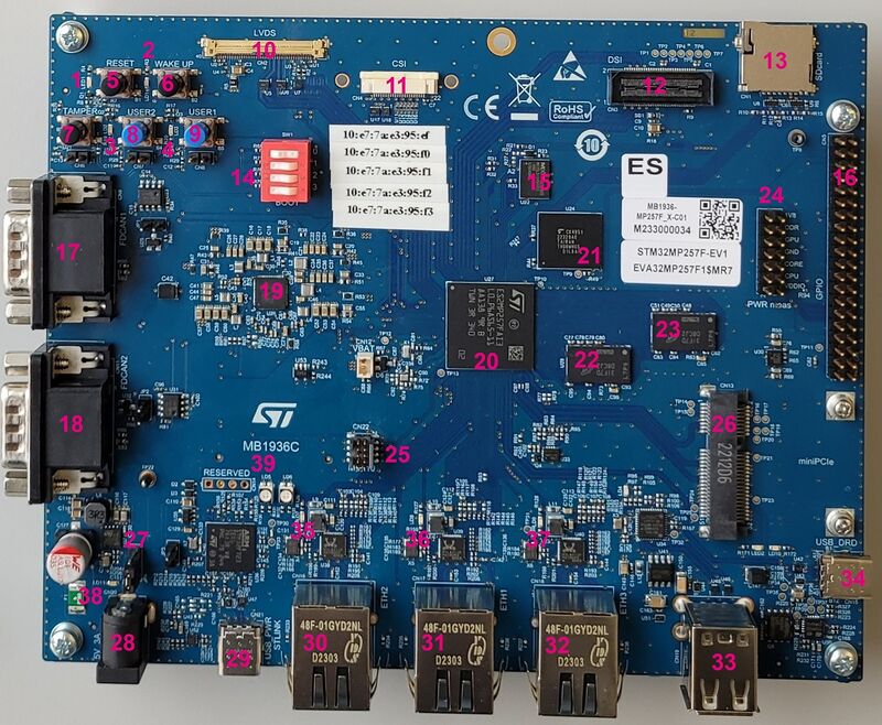
Main board MB1936, revision D-01: part of the STM32MP257x-EV1 Evaluation board ![]() .
.
It is highly recommended to work with a main board MB1936, revision D-01 instead of a main board MB1936, revision C-01, because the latter presents the following restrictions:
|
| Position | Description | Position | Description |
|---|---|---|---|
| 1 (LED1) | User LED (blue) [* 1] | 2 (LD1) | User LED (red) [* 1] |
| 3 (LD2) | User LED (orange) [* 1] | 4 (LD3) | User LED (green) [* 1] |
| 5 (B1) | RESET button | 6 (B2) | WAKE UP button |
| 7(B3) | TAMPER button | 8 (B4) | USER2 button |
| 9 (B5) | USER1 button | 10 (CN2) | LVDS connector |
| 11(CN4) | CSI connector | 12(CN3) | DSI connector |
| 13 (CN1) | microSD™ card connector | 14 (SW1) | Boot mode selection |
| 15 (U22) | S-NOR 512Mb | 16 (CN5) | GPIO expansion connector |
| 17 (CN9) | FDCAN1 | 18 (CN11) | FDCAN2 |
| 19 (U26) | STPMIC25 | 20 (U27) | STM32MP257 |
| 21 (U24) | eMMC 4GB | 22 (U29) | DDR4 2GB |
| 23(U28) | DDR4 2GB | 24 (CN10) | PWR measurements connector |
| 25 (CN22) | MIPI10 connector | 26 (CN13) | Mini-PCIe connector |
| 27 (JP4) | Power jumper | 28 (CN20) | 5V/3A power supply jack |
| 29 (CN21) | USB Power - ST-LINK Type-C | 30 (CN16) | ETHERNET 2 / PHY ETH2 |
| 31 (CN17) | ETHERNET 1 / PHY ETH1 | 32 (CN18) | ETHERNET 3 / PHY ETH3 |
| 33 (CN19) | Dual USB Host TypeA | 34 (CN15) | USB2.0 DRD Type-C |
| 35 (LD7) | Ethernet LED (green)[* 2] | 36 (LD8) | Ethernet LED (green)[* 2] |
| 37 (LD9) | Ethernet LED (green)[* 2] | 38 (LD11) | Power LED (green)[* 3] |
| 39 (LD5) | ST-LINK/V3-1 LED (bicolor)[* 4] | - | - |
Details about the LEDs:
- ↑ 1.0 1.1 1.2 1.3 LD2, LD3, LD4, LD5 (MB1936): some user LEDs are used to reflect the system activity, while others are left free for use by the application, as explained in the LEDs and buttons on STM32 MPU boards article.
- ↑ 2.0 2.1 2.2 LD7, LD8, LD9 (MB1936): these LEDs blink in green when an Ethernet connection has been established
- ↑ LD11 (MB1936): turns green when a power connection has been established.
- ↑ LD6 (MB1263): blinks in red if the ST-LINK/V3-1 connection was not established, otherwise it is green.
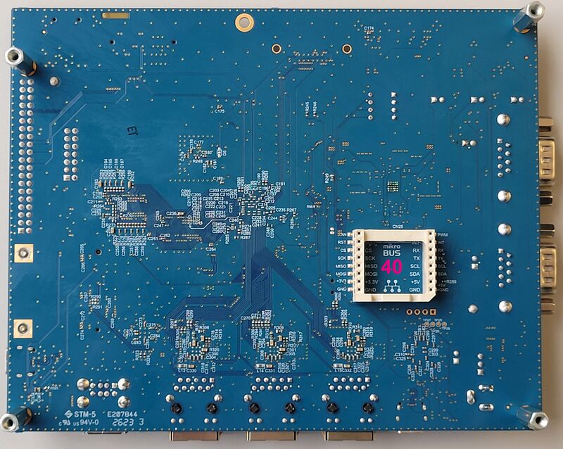
| Position | Description |
|---|---|
| 40 (CN25) | mikroBUS™ connector |
2. Links[edit | edit source]