This article explains how to assemble the STM32MP257x-DKx Discovery kits. It is valid for the STM32MP257F-DK ![]() Discovery kit: the part numbers are specified in the STM32MP25 microprocessor part numbers article.
Discovery kit: the part numbers are specified in the STM32MP25 microprocessor part numbers article.
The STM32MP257x-DKx Discovery kit package (STM32MP257F-DK ![]() ) contains the items listed below.
) contains the items listed below.
| Position | Description |
|---|---|
| 1 | MB1605 motherboard |
| 2 | microSD™ card |
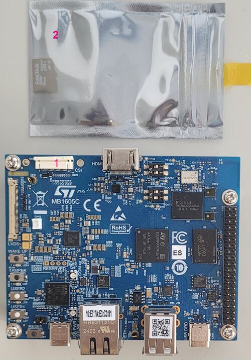
| LVDS displays and CSI cameras are available for purchase to complete this basic setup. |
The complete set contains:
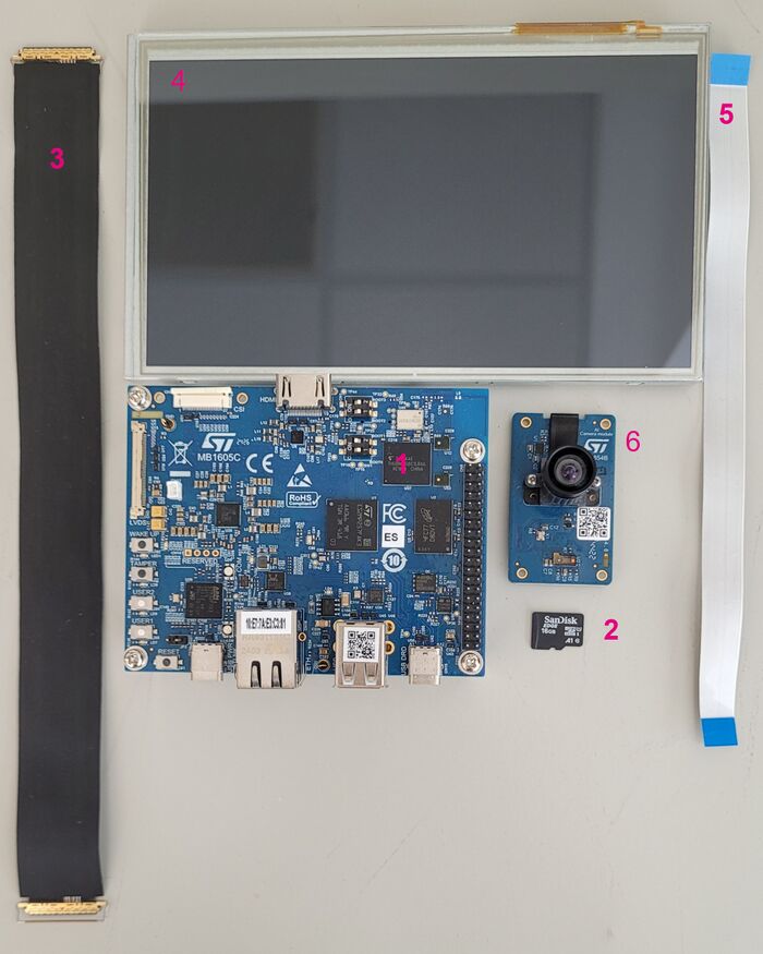
| Position | Description |
|---|---|
| 1 | MB1605 main board |
| 2 | MicroSD card |
| 3 | LVDS display cable (provided via B-LVDS7-WSVGA package) (optional) |
| 4 | 7” LVDS WSVGA display with EDT ETML0700Z9NDHA panel touch panel provided with the B-LVDS7-WSVGA package (optional) |
| 5 | Camera board FFC (provided with the B-CAMS-IMX package) (optional) |
| 6 | MB1854 board AI camera provided with the B-CAMS-IMX package (optional) |
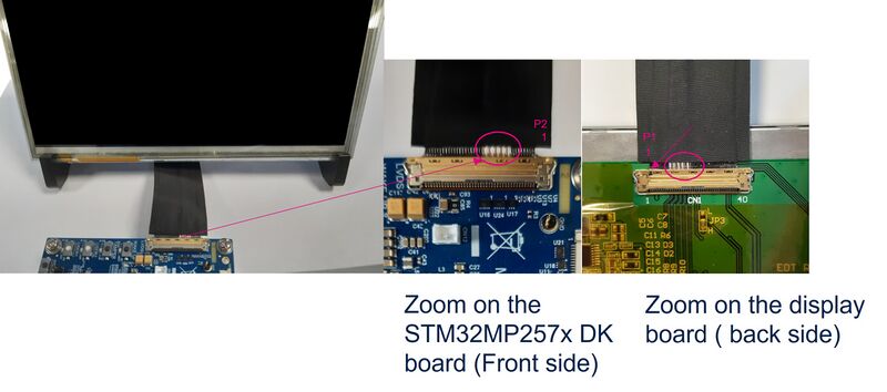
1. Connecting the LVDS display to the board (optional)[edit | edit source]
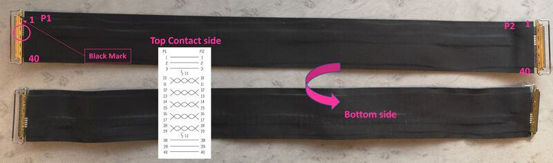
- Check the cable orientation shown above using the black mark and the white twisted pairs.
- Find the LVDS ports on the STM32MP257x-DK Discovery kit (CN2) and the display (CN1). The LVDS display box contains one cable.
- Insert the cable into each port as shown below:
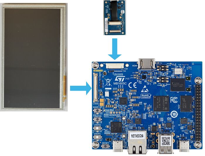
2. Connecting the MB1854 camera board to the board (optional)[edit | edit source]
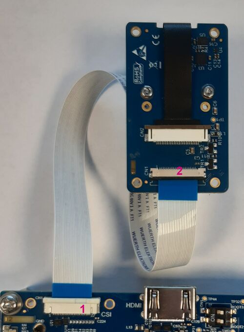
- Find the camera ports on the STM32MP257x-DK Discovery kit (CN8) (#1 in the image above) and MB1854 (CN1) (#2 in the image above). The camera box contains one FFC.
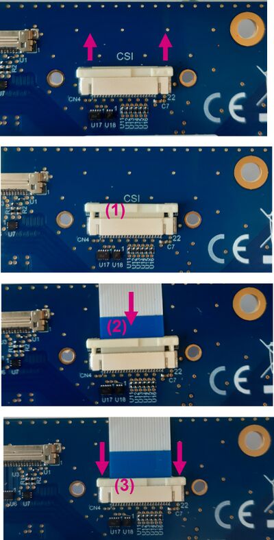
- For each port:
- Pull the black plastic (#1 in the image below) lightly to insert the contact side of the FFC towards the board (#2 in the image below).
- Push the black plastic carefully to hold the FFC (#3 in the image below).
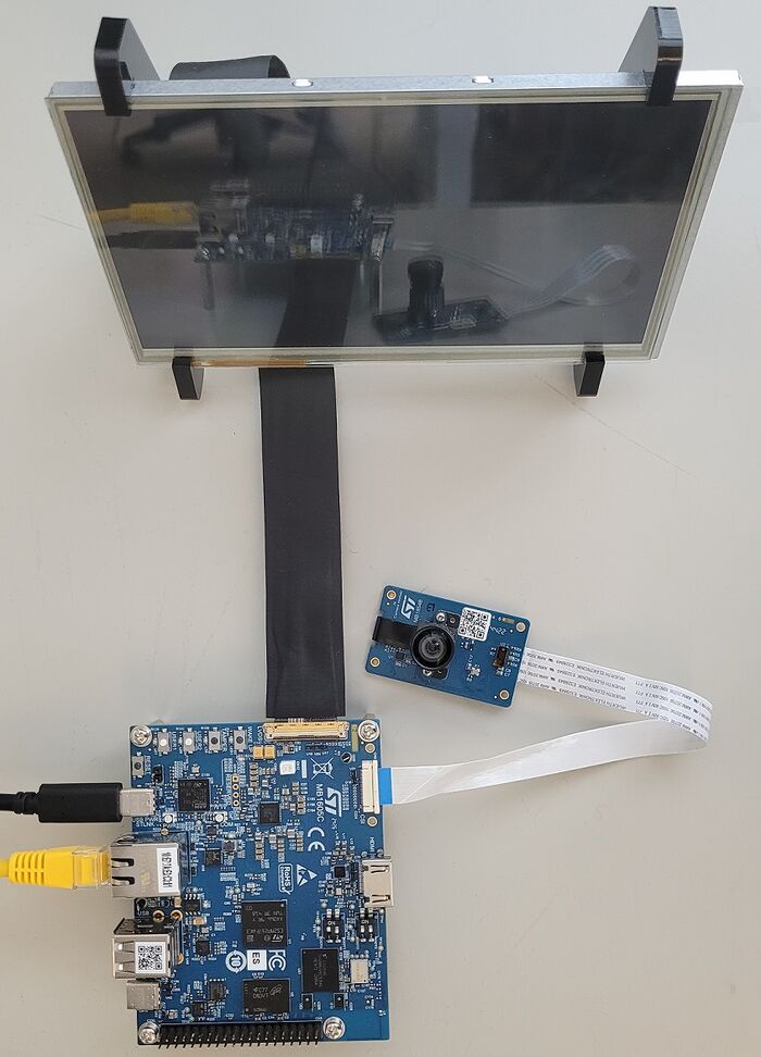
3. STM32MP257x-DK Discovery kit assembled[edit | edit source]